- 您現(xiàn)在的位置:買賣IC網(wǎng) > PDF目錄385396 > HSP50216 (Intersil Corporation) Four-Channel Programmable Digital DownConverter(四通道可編程數(shù)字下變頻器) PDF資料下載
參數(shù)資料
| 型號(hào): | HSP50216 |
| 廠商: | Intersil Corporation |
| 英文描述: | Four-Channel Programmable Digital DownConverter(四通道可編程數(shù)字下變頻器) |
| 中文描述: | 四通道可編程數(shù)字下變頻器(四通道可編程數(shù)字下變頻器) |
| 文件頁(yè)數(shù): | 29/52頁(yè) |
| 文件大小: | 431K |
| 代理商: | HSP50216 |
第1頁(yè)第2頁(yè)第3頁(yè)第4頁(yè)第5頁(yè)第6頁(yè)第7頁(yè)第8頁(yè)第9頁(yè)第10頁(yè)第11頁(yè)第12頁(yè)第13頁(yè)第14頁(yè)第15頁(yè)第16頁(yè)第17頁(yè)第18頁(yè)第19頁(yè)第20頁(yè)第21頁(yè)第22頁(yè)第23頁(yè)第24頁(yè)第25頁(yè)第26頁(yè)第27頁(yè)第28頁(yè)當(dāng)前第29頁(yè)第30頁(yè)第31頁(yè)第32頁(yè)第33頁(yè)第34頁(yè)第35頁(yè)第36頁(yè)第37頁(yè)第38頁(yè)第39頁(yè)第40頁(yè)第41頁(yè)第42頁(yè)第43頁(yè)第44頁(yè)第45頁(yè)第46頁(yè)第47頁(yè)第48頁(yè)第49頁(yè)第50頁(yè)第51頁(yè)第52頁(yè)
3-29
2:1
Number of Carrier Offset Frequency (COF) serial input bits.
00
01
10
11
8
16
24
32
0
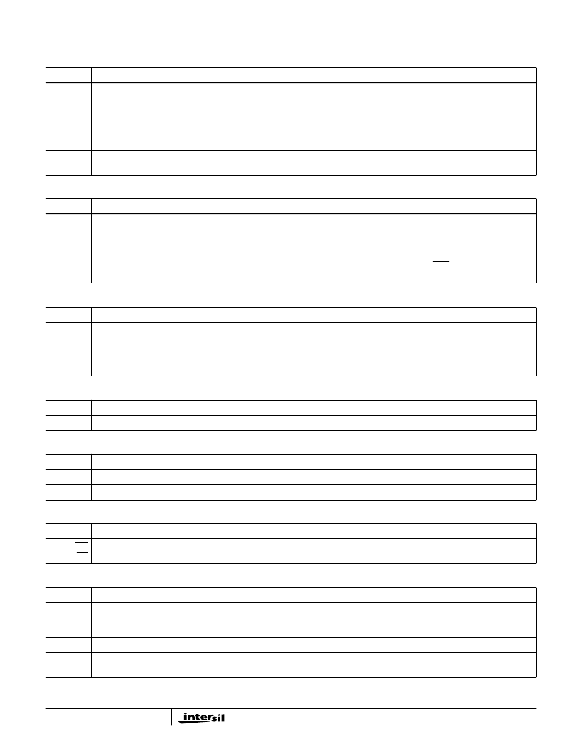
Enable serial offset frequency (zeros the data already loaded via the COF/COFSYNC pins). To disable the COF shifting see IWA
register *000h.
TABLE 5. CARRIER NCO/CIC CONTROL REGISTER (IWA = *004h) (Continued)
P(15:0)
FUNCTION
TABLE 6. CARRIER NCO CENTER FREQUENCY REGISTER (IWA = *005h)
P(15:0)
FUNCTION
31:0
Carrier Center Frequency (CCF)
This is the frequency control for the carrier NCO. The center frequency control is double buffered. The contents of this register are
transferred to the active register on a write to the CCFStrobe location or on a SYNCI (if load on SYNCI is enabled). The carrier center
frequency is: CCF*f
CLK
/(2
32
).
CCF is a twos complement number and has a range of -2
31
to (2
31
-1). f
CLK
is the input sample rate (ENIx assertion rate) for gated
mode and the clock rate for interpolated mode.
TABLE 7. CARRIER NCO CENTER FREQUENCY UPDATE STROBE REGISTER (IWA = *006h)
P(15:0)
FUNCTION
N/A
Writing to this address generates a strobe that transfers the CCF value to the active frequency register. The transfer to the active
register can also be done using the SYNCI pin to synchronize the transfer in multiple parts or to synchronize to an external event.
The value in the active register can be read at this address (the center frequency control before the serially loaded offset value is
added). To read the value, either write this address to A(1:0) = 11 and then read at A(1:0) = 00 and 01, or read the value at A(1:0) =
00 and 01 after writing to this address and before writing a new address to either A(1:0) = 10 or 11.
TABLE 8. TIMING NCO FREQUENCY CONTROL REGISTER, MSW (IWA = *007h)
P(15:0)
FUNCTION
31:0
These are the upper 32 bits of the 56-bit timing (resampler) NCO center frequency control.
TABLE 9. TIMING NCO FREQUENCY CONTROL REGISTER, LSW (IWA = *008h)
P(15:0)
FUNCTION
31:8
These are the lower 24 bits of the 56-bit timing (resampler) NCO center frequency control.
7:0
Unused, set to zero.
TABLE 10. TIMING NCO CENTER FREQUENCY LOAD STROBE REGISTER (IWA = *009h)
P(15:0)
FUNCTION
N/A for WR
31:0 for RD
A write to this location will update the resampler NCO center frequency. The upper 32 bits of the active register can be read at this
address.
TABLE 11. FILTER COMPUTE ENGINE/RESAMPLER CONTROL REGISTER (IWA = *00Ah)
P(15:0)
FUNCTION
31
μ
PHold. When set, this bit stops the filter compute engine and allows the
μ
P access to the instruction and coefficient RAMs for
reading and writing. On the high to low transition, the filter compute engine is reset (the read and write pointers are reset and the
instruction at location 31 is fetched).
30
μ
PShiftZeroB. This bit, when set to zero, disables the coefficient shift bits (bits 9:8 of the master register when coefficient loading).
29
μ
PENLimit. This bit disables the data path saturation logic. Provided for test. Active high. Set to 0 to disable the normal ROM
controlled limiting (ANDed with normal signal).
HSP50216
相關(guān)PDF資料 |
PDF描述 |
|---|---|
| HSP50307 | Burst QPSK Modulator(混合信號(hào)QPSK調(diào)制器) |
| HSP50415VI | CABLE ASSEMBLY; 75 OHM TNC MALE TO 75 OHM TNC MALE; 75 OHM, RG6A/U COAX |
| HSP50415EVAL1 | HSP50415EVAL1 Evaluation Kit |
| HSP9501 | Programmable Data Buffer(可編程數(shù)據(jù)緩沖器) |
| HSP9520 | Multilevel Pipeline Registers |
相關(guān)代理商/技術(shù)參數(shù) |
參數(shù)描述 |
|---|---|
| HSP50216_06 | 制造商:INTERSIL 制造商全稱:Intersil Corporation 功能描述:Four-Channel Programmable Digital DownConverter |
| HSP50216_07 | 制造商:INTERSIL 制造商全稱:Intersil Corporation 功能描述:Four-Channel Programmable Digital Downconverter |
| HSP50216KI | 功能描述:上下轉(zhuǎn)換器 MULTI-CHANNEL PROGRAMMABLE DOW CONVERTER,BGA PKG,IND TEMP RoHS:否 制造商:Texas Instruments 產(chǎn)品:Down Converters 射頻:52 MHz to 78 MHz 中頻:300 MHz LO頻率: 功率增益: P1dB: 工作電源電壓:1.8 V, 3.3 V 工作電源電流:120 mA 最大功率耗散:1 W 最大工作溫度:+ 85 C 安裝風(fēng)格:SMD/SMT 封裝 / 箱體:PQFP-128 |
| HSP50216KIZ | 功能描述:上下轉(zhuǎn)換器 MULTI-CH PROGRAM CONV BGA PKG IND RoHS:否 制造商:Texas Instruments 產(chǎn)品:Down Converters 射頻:52 MHz to 78 MHz 中頻:300 MHz LO頻率: 功率增益: P1dB: 工作電源電壓:1.8 V, 3.3 V 工作電源電流:120 mA 最大功率耗散:1 W 最大工作溫度:+ 85 C 安裝風(fēng)格:SMD/SMT 封裝 / 箱體:PQFP-128 |
| HSP50306 | 制造商:INTERSIL 制造商全稱:Intersil Corporation 功能描述:Digital QPSK Demodulator |
發(fā)布緊急采購(gòu),3分鐘左右您將得到回復(fù)。