- 您現(xiàn)在的位置:買賣IC網(wǎng) > PDF目錄369482 > BR1570 WarpLink Reference Design Platform PDF資料下載
參數(shù)資料
| 型號: | BR1570 |
| 英文描述: | WarpLink Reference Design Platform |
| 中文描述: | WarpLink參考設計平臺 |
| 文件頁數(shù): | 20/24頁 |
| 文件大小: | 492K |
| 代理商: | BR1570 |
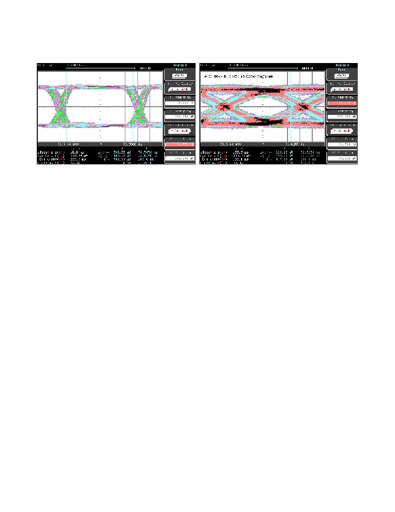
Figure 16(b), demonstrates the distortion seen for the differential pair S4_D1_D0-S4_D1_D0_P|N, a moderately long interconnect, 8.1
inches in total length, when compared to a reference path measurement, shown in Figure 16(a). The direct comparison allows us to
attribute the PCB interconnect of the WarpLink backplane and Test Card as the cause of the distortion in the eye opening.
WarpLink Reference Design Platform
20
For More Information On This Product,
Go to: www.freescale.com
(a) Reference Path
(b) S4_D1_D0-S4_D1_D0_[P|N]
Figure 16. Passive EYE Patterns
ACTIVE MEASUREMENT RESULTS
While the passive measurements quantify the quality of the passive transmission channels, the active measurements show how WarpLink
2.5 Quad performs over the same transmission channels. Active eye patterns driven by a WarpLink transmitter through a variety of
transmission channels of the system’s backplane were obtained. XAUI compliance was confirmed by overlaying the measured eye patterns
to the eye mask defined in the XAUI specification. The following sections describe the test setup and the various channels chosen for the
active measurements presented in the paper.
TEST SETUP
Eye diagrams from two different transmission channels are presented. The transmission channel connecting slot 8 and slot 1 was chosen
as an example of the longest, and thus worst case, backplane channel that was not artificially lengthened. The second transmission
channel chosen connects slot 7 and slot 1. This channel was artificially lengthened to present a condition that exceeds an interconnect
length defined by the XAUI standard.
A Line Card was installed in either slot 7 or 8. A Test Card from which the eye diagrams were obtained was in slot 1. The transmitter was
configured for the Built-in Self-Test (BIST) mode, configured for PN Equation 2 of the 23-bit PN generator (please refer to the WarpLink 2.5
Quad Product Brief for more details of the BIST mode). The full data path from a WarpLink transmitter on a Line Card in slots 7 or 8 to the
Test Card in slot 1 consisted of:
1. WarpLink Device
2. Package via
3. Line Card FR-4 trace
4. Line Card Connector Via
5. Line Card - Backplane ERmet ZD Connector
6. Backplane Connector Via
7. Backplane FR-4 trace
8. Backplane Connector Via
9. Backplane Connector
10. Test Card - Backplane ERmet ZD Connector
11. Test Card FR-4 trace
12. SMA Via
13. SMT - SMA Connector
14. SMA Right-Angle adapter
15. 36 inches of Rosenberger rf-coaxial cable
16. AC-coupling SMA adapter
17. TDS-8000 scope.
F
Freescale Semiconductor, Inc.
n
.
相關PDF資料 |
PDF描述 |
|---|---|
| BR200A | TRANSISTOR | BJT | NPN | 50V V(BR)CEO | 20A I(C) | TO-210AC |
| BR200B | TRANSISTOR | BJT | NPN | 50V V(BR)CEO | 20A I(C) | TO-210AC |
| BR201A | TRANSISTOR | BJT | NPN | 75V V(BR)CEO | 20A I(C) | TO-210AC |
| BR201B | TRANSISTOR | BJT | NPN | 75V V(BR)CEO | 20A I(C) | TO-210AC |
| BR211-140AMO | SINGLE BIDIRECTIONAL BREAKOVER DIODE|157V V(BO) MAX|1A I(S)|SOD-84 |
相關代理商/技術參數(shù) |
參數(shù)描述 |
|---|---|
| BR158 | 功能描述:橋式整流器 15A 800V RoHS:否 制造商:Vishay 產(chǎn)品:Single Phase Bridge 峰值反向電壓:1000 V 最大 RMS 反向電壓: 正向連續(xù)電流:4.5 A 最大浪涌電流:450 A 正向電壓下降:1 V 最大反向漏泄電流:10 uA 功率耗散: 最大工作溫度:+ 150 C 長度:30.3 mm 寬度:4.1 mm 高度:20.3 mm 安裝風格:Through Hole 封裝 / 箱體:SIP-4 封裝:Tube |
| BR158L | 制造商:GOOD-ARK 制造商全稱:GOOD-ARK Electronics 功能描述:SILICON BRIDGE RECTIFIERS |
| BR158W | 功能描述:橋式整流器 15A 800V Wire Lds RoHS:否 制造商:Vishay 產(chǎn)品:Single Phase Bridge 峰值反向電壓:1000 V 最大 RMS 反向電壓: 正向連續(xù)電流:4.5 A 最大浪涌電流:450 A 正向電壓下降:1 V 最大反向漏泄電流:10 uA 功率耗散: 最大工作溫度:+ 150 C 長度:30.3 mm 寬度:4.1 mm 高度:20.3 mm 安裝風格:Through Hole 封裝 / 箱體:SIP-4 封裝:Tube |
| BR15A | 制造商:Cooper Wiring Devices 功能描述: |
| BR15A601 | 制造商:Veeder-Root Company 功能描述: |
發(fā)布緊急采購,3分鐘左右您將得到回復。