- 您現(xiàn)在的位置:買賣IC網(wǎng) > PDF目錄98068 > S1C60A13F 4-BIT, MROM, 1.2 MHz, MICROCONTROLLER, PQFP80 PDF資料下載
參數(shù)資料
| 型號: | S1C60A13F |
| 元件分類: | 微控制器/微處理器 |
| 英文描述: | 4-BIT, MROM, 1.2 MHz, MICROCONTROLLER, PQFP80 |
| 封裝: | PLASTIC, QFP14-80 |
| 文件頁數(shù): | 40/104頁 |
| 文件大小: | 850K |
| 代理商: | S1C60A13F |
第1頁第2頁第3頁第4頁第5頁第6頁第7頁第8頁第9頁第10頁第11頁第12頁第13頁第14頁第15頁第16頁第17頁第18頁第19頁第20頁第21頁第22頁第23頁第24頁第25頁第26頁第27頁第28頁第29頁第30頁第31頁第32頁第33頁第34頁第35頁第36頁第37頁第38頁第39頁當前第40頁第41頁第42頁第43頁第44頁第45頁第46頁第47頁第48頁第49頁第50頁第51頁第52頁第53頁第54頁第55頁第56頁第57頁第58頁第59頁第60頁第61頁第62頁第63頁第64頁第65頁第66頁第67頁第68頁第69頁第70頁第71頁第72頁第73頁第74頁第75頁第76頁第77頁第78頁第79頁第80頁第81頁第82頁第83頁第84頁第85頁第86頁第87頁第88頁第89頁第90頁第91頁第92頁第93頁第94頁第95頁第96頁第97頁第98頁第99頁第100頁第101頁第102頁第103頁第104頁
32
EPSON
S1C60N13 TECHNICAL MANUAL
CHAPTER 4: PERIPHERAL CIRCUITS AND OPERATION (Serial Interface)
4.7 Serial Interface
4.7.1 Configuration of serial interface
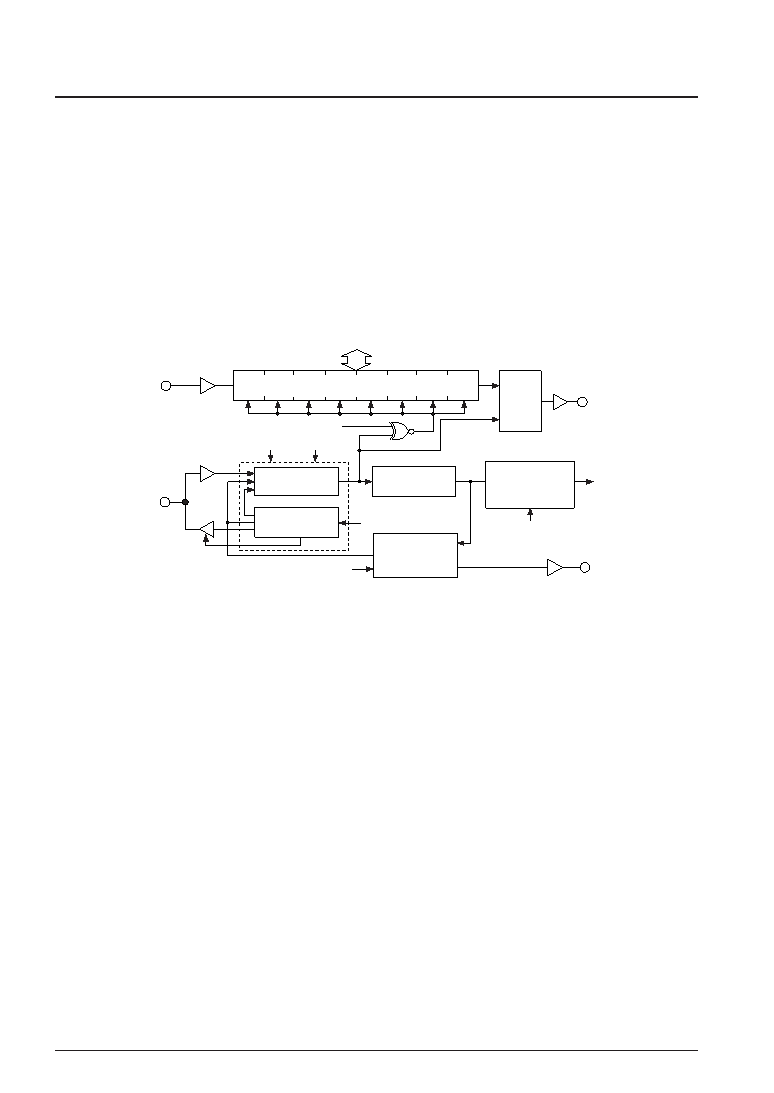
The S1C60N13 Series has a built-in synchronous clock type 8 bits serial interface that can be enabled by
mask option. The configuration of the serial interface is shown in Figure 4.7.1.1.
The CPU, via the 8 bits shift register, can read the serial input data from the SIN (P10) terminal. Moreover,
via the same 8 bits shift register, it can convert parallel data to serial data and output it to the SOUT (P11)
terminal. The synchronous clock for serial data input/output may be set by selecting by software any one
of 3 types of master mode (internal clock mode: when the S1C60N13 Series is to be the master for serial
input/output) and a type of slave mode (external clock mode: when the S1C60N13 Series is to be the
slave for serial input/output).
Also, when the serial interface is used at slave mode, SIOF (R11) signal which indicates whether or not
the serial interface is available to transmit or receive can be output to output port R11 by mask option.
SD0–SD7
SCS0
SCS1
SE2
Output
latch
EISIO
Serial I/F
interrupt control
circuit
ISIO
SIOF
(R11)
SCTRG
Serial I/F
activating
circuit
System clock
Serial clock
counter
Serial clock
selector
Shift register (8 bits)
Serial clock
generator
SOUT
(P11)
SIN
(P10)
SCLK
(P12)
Fig. 4.7.1.1 Configuration of serial interface
The SIN (P10) and SCLK (P12) terminals have a pull-down resistor. However, the SCLK (P12) terminal is
pulled down to low in external clock mode and the pull-down resistor is disabled in internal clock mode.
4.7.2 Mask option
The serial interface may be selected for the following by mask option.
(1) Whether the serial interface is used or not may be selected. When "use" is selected, the following I/O
port terminals are configured as the serial I/O terminals.
P10
→ SIN (data input)
P11
→ SOUT (data output)
P12
→ SCLK (clock input/output)
(2) Either complementary output or Pch open drain as output specification for the SOUT (P11) terminal
may be selected. However, even if Pch open drain has been selected, application of voltage exceeding
power source voltage to the SOUT (P11) terminal will be prohibited.
(3) As output specification during output mode, either complementary output or Pch open drain output
may be selected for the SCLK (P12) terminal.
(4) Positive or negative logic can be selected for the signal logic of the SIO function. However, keep in
mind that only pull-down resistance can be set for the input mode (pull-up resistance is not built-in).
(5) LSB first or MSB first as input/output permutation of serial data may be selected in the SIO function.
(6) Output port R11 may be assigned as SIOF (R11) output terminal which will indicate whether the serial
interface is available to transmit or receive signals.
相關(guān)PDF資料 |
PDF描述 |
|---|---|
| S1C60L16F0A0100 | 4-BIT, MROM, 0.032768 MHz, MICROCONTROLLER, PQFP80 |
| S1C60N01F | 4-BIT, MROM, 0.08 MHz, MICROCONTROLLER, PQFP48 |
| S1C60N02D | 4-BIT, MROM, 0.08 MHz, MICROCONTROLLER, UUC52 |
| S1C60L02 | 4-BIT, MROM, 0.08 MHz, MICROCONTROLLER, PQFP60 |
| S1C60N04D | 4-BIT, MROM, 2 MHz, MICROCONTROLLER, UUC48 |
相關(guān)代理商/技術(shù)參數(shù) |
參數(shù)描述 |
|---|---|
| S1C60A16 | 制造商:EPSON 制造商全稱:EPSON 功能描述:4-bit Single Chip Microcomputer |
| S1C60L05 | 制造商:EPSON 制造商全稱:EPSON 功能描述:4-bit Single Chip Microcomputer |
| S1C60L08 | 制造商:EPSON 制造商全稱:EPSON 功能描述:4-bit Single Chip Microcomputer |
| S1C60L16 | 制造商:EPSON 制造商全稱:EPSON 功能描述:4-bit Single Chip Microcomputer |
| S1C60N05 | 制造商:EPSON 制造商全稱:EPSON 功能描述:4-bit Single Chip Microcomputer |
發(fā)布緊急采購,3分鐘左右您將得到回復(fù)。