- 您現(xiàn)在的位置:買賣IC網(wǎng) > PDF目錄98011 > MC56F8355MFG60 (MOTOROLA INC) 4-BIT, 120 MHz, OTHER DSP, PQFP128 PDF資料下載
參數(shù)資料
| 型號: | MC56F8355MFG60 |
| 廠商: | MOTOROLA INC |
| 元件分類: | 數(shù)字信號處理 |
| 英文描述: | 4-BIT, 120 MHz, OTHER DSP, PQFP128 |
| 封裝: | LQFP-128 |
| 文件頁數(shù): | 74/152頁 |
| 文件大小: | 2224K |
| 代理商: | MC56F8355MFG60 |
第1頁第2頁第3頁第4頁第5頁第6頁第7頁第8頁第9頁第10頁第11頁第12頁第13頁第14頁第15頁第16頁第17頁第18頁第19頁第20頁第21頁第22頁第23頁第24頁第25頁第26頁第27頁第28頁第29頁第30頁第31頁第32頁第33頁第34頁第35頁第36頁第37頁第38頁第39頁第40頁第41頁第42頁第43頁第44頁第45頁第46頁第47頁第48頁第49頁第50頁第51頁第52頁第53頁第54頁第55頁第56頁第57頁第58頁第59頁第60頁第61頁第62頁第63頁第64頁第65頁第66頁第67頁第68頁第69頁第70頁第71頁第72頁第73頁當(dāng)前第74頁第75頁第76頁第77頁第78頁第79頁第80頁第81頁第82頁第83頁第84頁第85頁第86頁第87頁第88頁第89頁第90頁第91頁第92頁第93頁第94頁第95頁第96頁第97頁第98頁第99頁第100頁第101頁第102頁第103頁第104頁第105頁第106頁第107頁第108頁第109頁第110頁第111頁第112頁第113頁第114頁第115頁第116頁第117頁第118頁第119頁第120頁第121頁第122頁第123頁第124頁第125頁第126頁第127頁第128頁第129頁第130頁第131頁第132頁第133頁第134頁第135頁第136頁第137頁第138頁第139頁第140頁第141頁第142頁第143頁第144頁第145頁第146頁第147頁第148頁第149頁第150頁第151頁第152頁
28
56F8355 Technical Data
Preliminary
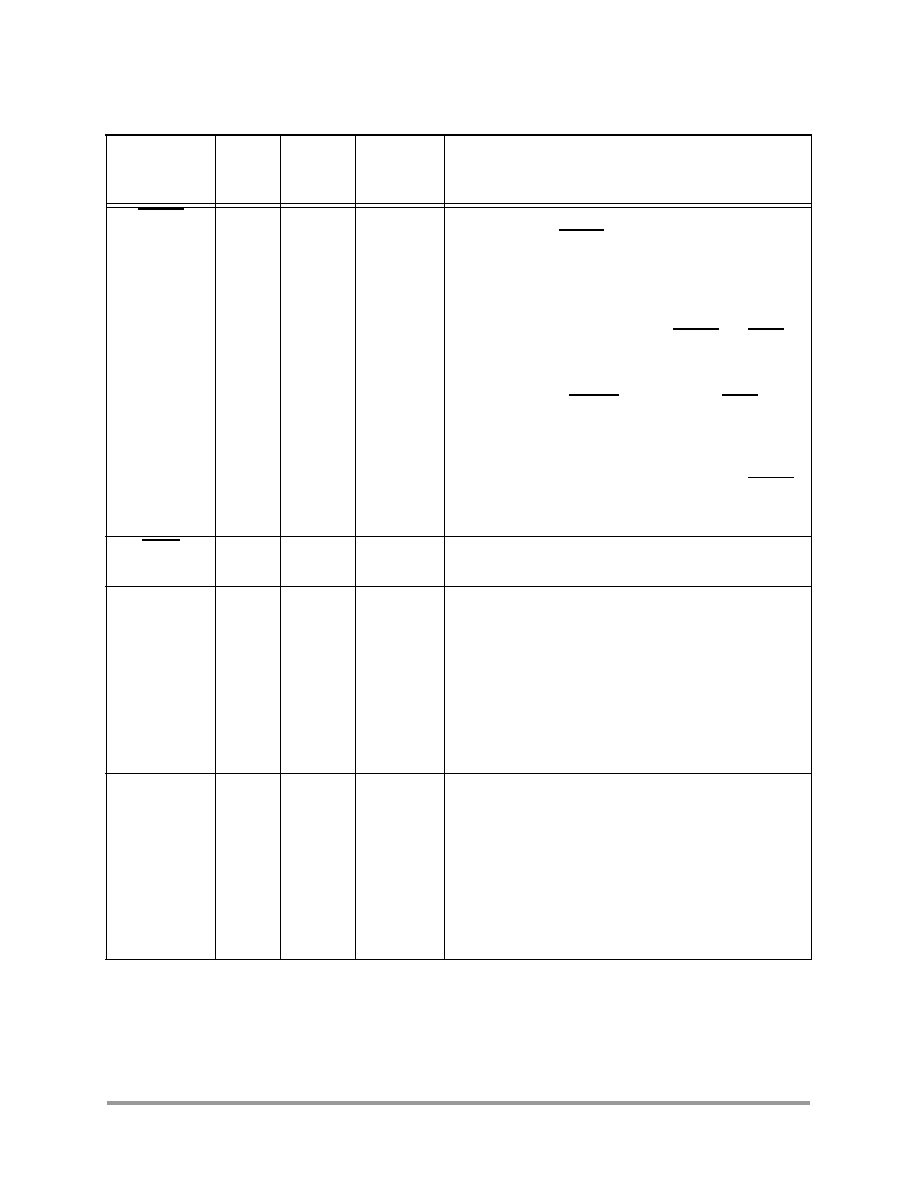
RESET
78
Schmitt
Input
Reset — This input is a direct hardware reset on the
processor. When RESET is asserted low, the device is
initialized and placed in the reset state. A Schmitt trigger
input is used for noise immunity. The internal reset signal
will be deasserted synchronous with the internal clocks
after a fixed number of internal clocks.
To ensure complete hardware reset, RESET and TRST
should be asserted together. The only exception occurs in
a debugging environment when a hardware device reset is
required and the JTAG/EOnCE module must not be reset.
In this case, assert RESET but do not assert TRST.
Note: The internal Power-On Reset will assert on initial
power-up.
To deactivate the internal pull-up resistor, set the RESET
bit in the SIM_PUDR register. See Section 6.5.6 for
details.
RSTO
77
Output
Reset Output — This output reflects the internal reset
state of the chip.
EXTBOOT
Internal
Ground
Schmitt
Input
External Boot — This input is tied to VDD to force the
device to boot from off-chip memory (assuming that the
on-chip Flash memory is not in a secure state). Otherwise,
it is tied to ground. For details, see Table 4-4.
Note: When this pin is tied low, the customer boot software
should disable the internal pull-up resistor by setting the
XBOOT bit of the SIM_PUDR; see Section 6.5.6.
Note: This pin is internally tied low (to VSS).
EMI_MODE
Internal
Ground
Schmitt
Input
External Memory Mode — This device will boot from
internal Flash memory under normal operation.
This function is also affected by EXTBOOT and the Flash
security mode; see Table 4-4 for details.
Note: When this pin is tied low, the customer boot software
should disable the internal pull-up resistor by setting the
EMI_MODE bit of the SIM_PUDR; see Section 6.5.6.
Note: This pin is internally tied low (to VSS).
Table 2-2 56F8355 Signal and Package Information for the 128-Pin LQFP
Signal Name
Pin No.
Type
State
During
Reset
Signal Description
相關(guān)PDF資料 |
PDF描述 |
|---|---|
| MC6805R2CP | 8-BIT, MROM, MICROCONTROLLER, PDIP40 |
| MC68302PV25C | LOCAL AREA NETWORK CONTROLLER, PQFP144 |
| MC68302PV25C | LOCAL AREA NETWORK CONTROLLER, PQFP144 |
| MC68306PV16 | 32-BIT, 16.67 MHz, MICROPROCESSOR, PQFP144 |
| MC68450LC-8 | 4 CHANNEL(S), 8 MHz, DMA CONTROLLER, CDIP64 |
相關(guān)代理商/技術(shù)參數(shù) |
參數(shù)描述 |
|---|---|
| MC56F8355MFGE | 功能描述:數(shù)字信號處理器和控制器 - DSP, DSC 16 BIT HYBRID CONTROLLER RoHS:否 制造商:Microchip Technology 核心:dsPIC 數(shù)據(jù)總線寬度:16 bit 程序存儲器大小:16 KB 數(shù)據(jù) RAM 大小:2 KB 最大時鐘頻率:40 MHz 可編程輸入/輸出端數(shù)量:35 定時器數(shù)量:3 設(shè)備每秒兆指令數(shù):50 MIPs 工作電源電壓:3.3 V 最大工作溫度:+ 85 C 封裝 / 箱體:TQFP-44 安裝風(fēng)格:SMD/SMT |
| MC56F8355VFG60 | 制造商:FREESCALE 制造商全稱:Freescale Semiconductor, Inc 功能描述:16-bit Hybrid Controllers |
| MC56F8355VFGE | 功能描述:數(shù)字信號處理器和控制器 - DSP, DSC 16 BIT HYBRID CNTRLR RoHS:否 制造商:Microchip Technology 核心:dsPIC 數(shù)據(jù)總線寬度:16 bit 程序存儲器大小:16 KB 數(shù)據(jù) RAM 大小:2 KB 最大時鐘頻率:40 MHz 可編程輸入/輸出端數(shù)量:35 定時器數(shù)量:3 設(shè)備每秒兆指令數(shù):50 MIPs 工作電源電壓:3.3 V 最大工作溫度:+ 85 C 封裝 / 箱體:TQFP-44 安裝風(fēng)格:SMD/SMT |
| MC56F8356 | 制造商:MOTOROLA 制造商全稱:Motorola, Inc 功能描述:56F8356 16-bit Hybrid Controller |
| MC56F8356MFV60 | 制造商:Rochester Electronics LLC 功能描述:- Bulk |
發(fā)布緊急采購,3分鐘左右您將得到回復(fù)。