- 您現(xiàn)在的位置:買賣IC網(wǎng) > PDF目錄370612 > HM17CM4096 (Electronic Theatre Controls, Inc.) 128XRGBX162 OUTPUT LCD DRIVER IC with built-in RAM PDF資料下載
參數(shù)資料
| 型號: | HM17CM4096 |
| 廠商: | Electronic Theatre Controls, Inc. |
| 英文描述: | 128XRGBX162 OUTPUT LCD DRIVER IC with built-in RAM |
| 中文描述: | 128XRGBX162輸出LCD驅動器內置內存 |
| 文件頁數(shù): | 56/67頁 |
| 文件大小: | 1117K |
| 代理商: | HM17CM4096 |
第1頁第2頁第3頁第4頁第5頁第6頁第7頁第8頁第9頁第10頁第11頁第12頁第13頁第14頁第15頁第16頁第17頁第18頁第19頁第20頁第21頁第22頁第23頁第24頁第25頁第26頁第27頁第28頁第29頁第30頁第31頁第32頁第33頁第34頁第35頁第36頁第37頁第38頁第39頁第40頁第41頁第42頁第43頁第44頁第45頁第46頁第47頁第48頁第49頁第50頁第51頁第52頁第53頁第54頁第55頁當前第56頁第57頁第58頁第59頁第60頁第61頁第62頁第63頁第64頁第65頁第66頁第67頁
HM17CM4096
- 56 -
Applied port (* Remark Solves)
*1
*2
*3
*4
*5
*6
D
0
~D
15
, CS, RS, M/S, RD, WR, P/S, SEL68, CLK, CL, FLM, FR, RES ports
D
0
~D
15
ports
CL, FLM, FR, CLK ports
CS, RS, M/S, SEL68, RD, WR, P/S, RES, OSC
1
ports
applicable at D
0
~D
15
, CL, FLM, FR, CLK = high impedance state
SEGA
0
~SEGA
127
, SEGB
0
~SEGB
127
, SEGC
0
~SEGC
127
, COM
0
~COM
79
, COMI
0
, COMI
1
ports
resistance when being supplied 0.5V between each output ports and power port (V
LCD,
V
1,
V
2,
V
3,
V
4
)
applicable under bias ratio = 1/9
V
DD
ports
V
DD
current when source clock is stopped, chip selection (CS=V
DD
) is non-selection state and no load.
oscillator frequency when internal oscillator circuit is used ( gradation display mode).
applicable under Rf register of oscillator circuit, {Rf
2
, Rf
1
, Rf
0
} = “000”
oscillator frequency when internal oscillator circuit is used ( fixed gradation display mode).
applicable under Rf register of oscillator circuit, {Rf
2
, Rf
1
, Rf
0
} = “000”
*10 oscillator frequency when internal oscillator circuit is used ( BW display mode).
applicable under Rf register of oscillator circuit, {Rf
2
, Rf
1
, Rf
0
} = “000”
*11 VDD
*7
*8
*9
3
25
!
*12 V
OUT
port
N x boosting (N=2~7). applicable under internal oscillator circuit and internal power circuit are ON state
V
= 2.4~3.3V, electric volume is MAX(“1111111”).
bias = 1/5~1/10, 1/82 duty, no load at LCD driver port.
RL = 500k
(between V
OUT
,V
SS
), CA
1
= CA
2
=1.0
μ
F, CA
3
=0.1
μ
F, DCON=“1”, AMPON=“1”
*13 applicable under internal oscillator circuit and internal power circuit are ON state and no access from
CPU.
electric volume is “1111111”.
Display is all ON and cross check pattern display ( variable gradation display mode), and no load at
LCD driver port.
Test condition : V
DD
=V
EE
, V
REF
=0.9V
EE
, CA
1
=CA
2
=1.0
μ
F, CA
3
=0.1
μ
F, DCON=“1”, AMPON=“1”,
NLIN=”0”, 1/82 duty. Ta=25
*14 V
REG
output voltage when V
BA
output is connected to V
REF
input, V
REG
gain is N=1.
force VOUT=13.5V with DCON=”0”
*15 V
REG
port
V
EE
= 2.4~3.3V, V
REF
= 0.9 V
EE
, bias= 1/5~1/10, 1/82 duty, electric volume is “1111111”
Cross check pattern state and no load at LCD driver port.
Boosting coefficient N is 2~7 times
Test condition : CA
1
=CA
2
=1.0
μ
F, CA
3
=0.1
μ
F, DCON=“1”, AMPON=“1”, NLIN=”0”
*16 V
LCD
V
1
V
2
V
3
V
4
port
V
EE
= 3.0V, V
REF
= 0.9 V
EE
,
Display OFF and no load at LCD drive port.
Boosting coefficient N is 5 times.
Test condition : CA
2
=1.0
μ
F, CA
3
=0.1
μ
F, DCON=“0”, AMPON=“1”
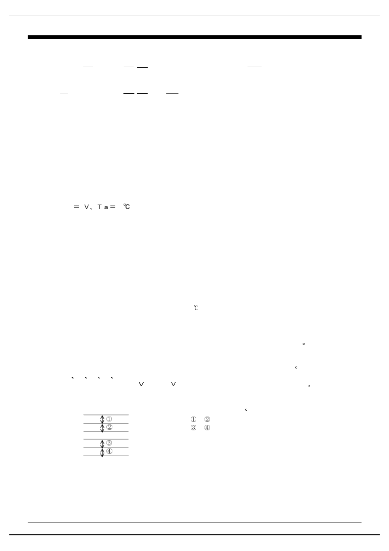
V
D12
=
V
D34
=
V
2
V
3
V
4
V
SS
#
#
out=13.5
, bias = 1/5~1/10, electric volume is “1111111”
#
#
&
'
-
-
(
(
)
*
+
*
V
1
V
LCD
相關PDF資料 |
PDF描述 |
|---|---|
| HM18-40004 | EE Style Common-Mode Chokes |
| HM18 | EE Style Common-Mode Chokes |
| HM18-10001 | EE Style Common-Mode Chokes |
| HM18-10002 | EE Style Common-Mode Chokes |
| HM18-10003 | EE Style Common-Mode Chokes |
相關代理商/技術參數(shù) |
參數(shù)描述 |
|---|---|
| HM18 | 制造商:BITECH 制造商全稱:Bi technologies 功能描述:Common-Mode Chokes |
| HM180K | 制造商:Ohmite Mfg Co 功能描述: |
| HM18-10001 | 制造商:未知廠家 制造商全稱:未知廠家 功能描述:EE Style Common-Mode Chokes |
| HM18-10002 | 制造商:未知廠家 制造商全稱:未知廠家 功能描述:EE Style Common-Mode Chokes |
| HM18-10003 | 制造商:未知廠家 制造商全稱:未知廠家 功能描述:EE Style Common-Mode Chokes |
發(fā)布緊急采購,3分鐘左右您將得到回復。