- 您現(xiàn)在的位置:買賣IC網(wǎng) > PDF目錄384296 > EM78568 (Electronic Theatre Controls, Inc.) 8-BIT MICRO-CONTROLLER for FRS PDF資料下載
參數(shù)資料
| 型號(hào): | EM78568 |
| 廠商: | Electronic Theatre Controls, Inc. |
| 英文描述: | 8-BIT MICRO-CONTROLLER for FRS |
| 中文描述: | 8位微控制器為FRS |
| 文件頁數(shù): | 20/54頁 |
| 文件大小: | 494K |
| 代理商: | EM78568 |
第1頁第2頁第3頁第4頁第5頁第6頁第7頁第8頁第9頁第10頁第11頁第12頁第13頁第14頁第15頁第16頁第17頁第18頁第19頁當(dāng)前第20頁第21頁第22頁第23頁第24頁第25頁第26頁第27頁第28頁第29頁第30頁第31頁第32頁第33頁第34頁第35頁第36頁第37頁第38頁第39頁第40頁第41頁第42頁第43頁第44頁第45頁第46頁第47頁第48頁第49頁第50頁第51頁第52頁第53頁第54頁

EM78568
8-bit Micro-controller for FRS
__________________________________________________________________________________________________________________________________________________________________
* This specification are subject to be changed without notice.
07/28/2004 V3.5
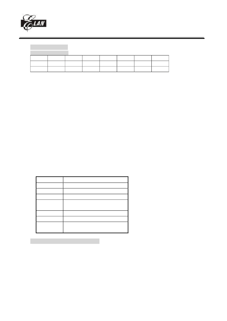
RF (Interrupt status)
(Interrupt status register)
7
INT3
R/W-0
"1" means interrupt request, "0" means non-interrupt
Bit 0(TCIF) : TCC timer overflow interrupt flag
Set when TCC timer overflows.
Bit 1(CNT1) : counter1 timer overflow interrupt flag
Set when counter1 timer overflows.
Bit 2(CNT2) : counter2 timer overflow interrupt flag
Set when counter2 timer overflows.
Bit 3(INT0) : external INT0 pin interrupt flag
If PORT70 has a falling edge/rising edge (controlled by CONT register) trigger signal, CPU will set this bit.
Bit 4(INT1) : external INT1 pin interrupt flag
If PORT71 has a falling edge trigger signal, CPU will set this bit.
Bit 5(INT2) : external INT2 pin interrupt flag
If PORT72 has a falling edge trigger signal, CPU will set this bit.
Bit 6(DETO) : CTCSS tone detection interrupt flag
If CTCSS detection output signal(R7 PAGE1 bit 6) has an edge signal (falling edge, falling and rising
edge), CPU will set this bit.
Bit 7(INT3) : external INT3 pin interrupt flag
If PORT73 has a falling edge trigger signal, CPU will set this bit.
<Note> IOCF is the interrupt mask register. User can read and clear.
Trigger edge as the table
Signal
Trigger
TCC
Time out
COUNTER1
Time out
COUNTER2
Time out
INT0
Falling
Rising edge
INT1
Falling edge
INT2
Falling edge
DETO
Falling edge
Falling and rising edge
R10~R3F (General Purpose Register)
R10~R3F (Banks 0 ~ 3) : all are general purpose registers.
6
5
4
3
2
1
0
DETO
R/W-0
INT2
R/W-0
INT1
R/W-0
INT0
R/W-0
CNT2
R/W-0
CNT1
R/W-0
TCIF
R/W-0
相關(guān)PDF資料 |
PDF描述 |
|---|---|
| EMA2 | Emitter common (dual digital transistors) |
| EMA3 | Emitter common (dual digital transistors) |
| EMA4 | General purpose (dual digital transistors) |
| EMB4 | General purpose (dual digital transistors) |
| EMA5 | Emitter common (dual digital transistors) |
相關(guān)代理商/技術(shù)參數(shù) |
參數(shù)描述 |
|---|---|
| EM78569 | 制造商:EMC 制造商全稱:ELAN Microelectronics Corp 功能描述:8-BIT MICRO-CONTROLLER |
| EM785830AA | 制造商:EMC 制造商全稱:ELAN Microelectronics Corp 功能描述:8-BIT MICRO-CONTROLLER |
| EM785830AAM | 制造商:EMC 制造商全稱:ELAN Microelectronics Corp 功能描述:8-BIT MICRO-CONTROLLER |
| EM785830AAP | 制造商:EMC 制造商全稱:ELAN Microelectronics Corp 功能描述:8-BIT MICRO-CONTROLLER |
| EM785830AD | 制造商:EMC 制造商全稱:ELAN Microelectronics Corp 功能描述:8-BIT MICRO-CONTROLLER |
發(fā)布緊急采購,3分鐘左右您將得到回復(fù)。