- 您現(xiàn)在的位置:買賣IC網(wǎng) > PDF目錄20614 > USB-EA-CONVZ (Analog Devices Inc)SUPPORT BOARD ADUC8XX PDF資料下載
參數(shù)資料
| 型號(hào): | USB-EA-CONVZ |
| 廠商: | Analog Devices Inc |
| 文件頁數(shù): | 58/68頁 |
| 文件大小: | 0K |
| 描述: | SUPPORT BOARD ADUC8XX |
| 標(biāo)準(zhǔn)包裝: | 1 |
| 類型: | 仿真器 |
| 適用于相關(guān)產(chǎn)品: | ADuC8xx |
| 所含物品: | 模塊 |
第1頁第2頁第3頁第4頁第5頁第6頁第7頁第8頁第9頁第10頁第11頁第12頁第13頁第14頁第15頁第16頁第17頁第18頁第19頁第20頁第21頁第22頁第23頁第24頁第25頁第26頁第27頁第28頁第29頁第30頁第31頁第32頁第33頁第34頁第35頁第36頁第37頁第38頁第39頁第40頁第41頁第42頁第43頁第44頁第45頁第46頁第47頁第48頁第49頁第50頁第51頁第52頁第53頁第54頁第55頁第56頁第57頁當(dāng)前第58頁第59頁第60頁第61頁第62頁第63頁第64頁第65頁第66頁第67頁第68頁
REV. B
ADuC824
–61–
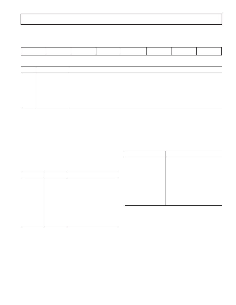
IEIP2
Secondary Interrupt Enable and Priority Register
SFR Address
A9H
Power-On Default Value
A0H
Bit Addressable
No
—
I
T
PM
S
P
PI
S
P
—
I
T
EM
S
P
EI
S
E
Table XXXII. IEIP2 SFR Bit Designations
Bit
Name
Description
7
—
Reserved for Future Use
6
PTI
Written by User to Select TIC Interrupt Priority (‘1’ = High; ‘0’ = Low).
5
PPSM
Written by User to Select Power Supply Monitor Interrupt Priority (‘1’ = High; ‘0’ = Low).
4
PSI
Written by User to Select SPI/I
2C Serial Port Interrupt Priority (‘1’ = High; ‘0’ = Low).
3
—
Reserved, This Bit Must Be ‘0.’
2
ETI
Written by User to Enable ‘1’ or Disable ‘0’ TIC Interrupt.
1
EPSM
Written by User to Enable ‘1’ or Disable ‘0’ Power Supply Monitor Interrupt.
0
ESI
Written by User to Enable ‘1’ or Disable ‘0’ SPI/I
2C Serial Port Interrupt.
Interrupt Priority
The Interrupt Enable registers are written by the user to enable
individual interrupt sources, while the Interrupt Priority registers
allow the user to select one of two priority levels for each interrupt. An
interrupt of a high priority may interrupt the service routine of a low
priority interrupt, and if two interrupts of different priority occur
at the same time, the higher level interrupt will be serviced first. An
interrupt cannot be interrupted by another interrupt of the same
priority level. If two interrupts of the same priority level occur simulta-
neously, a polling sequence is observed as shown in Table XXXIII.
Table XXXIII. Priority within an Interrupt Level
Source
Priority
Description
PSMI
1 (Highest)
Power Supply Monitor Interrupt
WDS
2
Watchdog Interrupt
IE0
3
External Interrupt 0
RDY0/RDY1
4
ADC Interrupt
TF0
5
Timer/Counter 0 Interrupt
IE1
6
External Interrupt 1
TF1
7
Timer/Counter 1 Interrupt
I2CI + ISPI
8
I
2C/SPI Interrupt
RI + TI
9
Serial Interrupt
TF2 + EXF2
10
Timer/Counter 2 Interrupt
TII
11 (Lowest)
Time Interval Counter Interrupt
Interrupt Vectors
When an interrupt occurs the program counter is pushed onto the
stack and the corresponding interrupt vector address is loaded into
the program counter. The interrupt vector addresses are shown
in Table XXXIV.
Table XXXIV. Interrupt Vector Addresses
Source
Vector Address
IE0
0003 Hex
TF0
000B Hex
IE1
0013 Hex
TF1
001B Hex
RI + TI
0023 Hex
TF2 + EXF2
002B Hex
RDY0/RDY1 (ADC)
0033 Hex
II
2C + ISPI
003B Hex
PSMI
0043 Hex
TII
0053 Hex
WDS (WDIR = 1)
*
005B Hex
*The watchdog can be configured to generate an interrupt instead of a reset when it
times out. This is used for logging errors or to examine the internal status of the
microcontroller core to understand, from a software debug point of view, why a
watchdog timeout occurred. The watchdog interrupt is slightly different from the
normal interrupts in that its priority level is always set to 1 and it is not possible
to disable the interrupt via the global disable bit ( EA) in the IE SFR. This is
done to ensure that the interrupt will always be responded to if a watch dog
timeout occurs. The watchdog will only produce an interrupt if the watchdog
timeout is greater than zero.
相關(guān)PDF資料 |
PDF描述 |
|---|---|
| RGP10KE-E3/54 | DIODE GPP 1A 800V 500NS DO-41 |
| A7NXB-1506G | CABLE D-SUB - AMN15B/AE15G/X |
| C1005C0G1H470J | CAP CER 47PF 50V 5% NP0 0402 |
| SLF6045T-220M1R1-3PF | INDUCTOR POWER 22UH 1.1A SMD |
| GBM12DRTI-S13 | CONN EDGECARD 24POS .156 EXTEND |
相關(guān)代理商/技術(shù)參數(shù) |
參數(shù)描述 |
|---|---|
| USB-ETH ADAPTER | 制造商:DANAHER - FLUKE 功能描述:USB TO 10/100MBPS ETHERNET ADAPTER |
| USB-ETHERNET-AX88772B | 制造商:Olimex 功能描述:USB ETH ADAPTOR OLINUXINO |
| USB-EVAL | 功能描述:界面開發(fā)工具 USB products evalua- tion board unpopultd RoHS:否 制造商:Bourns 產(chǎn)品:Evaluation Boards 類型:RS-485 工具用于評(píng)估:ADM3485E 接口類型:RS-485 工作電源電壓:3.3 V |
| USBEX02 | 制造商:Distributed By MCM 功能描述:15' USB 2.0 Active Extension Cable |
| USBEXT-150 | 制造商:DigitHead Inc 功能描述:USB EXTENDER 150' |
發(fā)布緊急采購(gòu),3分鐘左右您將得到回復(fù)。