- 您現(xiàn)在的位置:買賣IC網(wǎng) > PDF目錄200645 > UPD62AMC-XXX-5A4-A 4-BIT, MROM, 4 MHz, MICROCONTROLLER, PDSO20 PDF資料下載
參數(shù)資料
| 型號: | UPD62AMC-XXX-5A4-A |
| 元件分類: | 微控制器/微處理器 |
| 英文描述: | 4-BIT, MROM, 4 MHz, MICROCONTROLLER, PDSO20 |
| 封裝: | 0.300 INCH, PLASTIC, SSOP-20 |
| 文件頁數(shù): | 56/62頁 |
| 文件大?。?/td> | 272K |
| 代理商: | UPD62AMC-XXX-5A4-A |
第1頁第2頁第3頁第4頁第5頁第6頁第7頁第8頁第9頁第10頁第11頁第12頁第13頁第14頁第15頁第16頁第17頁第18頁第19頁第20頁第21頁第22頁第23頁第24頁第25頁第26頁第27頁第28頁第29頁第30頁第31頁第32頁第33頁第34頁第35頁第36頁第37頁第38頁第39頁第40頁第41頁第42頁第43頁第44頁第45頁第46頁第47頁第48頁第49頁第50頁第51頁第52頁第53頁第54頁第55頁當(dāng)前第56頁第57頁第58頁第59頁第60頁第61頁第62頁
6
PD62A
Data Sheet U14474EJ2V0DS00
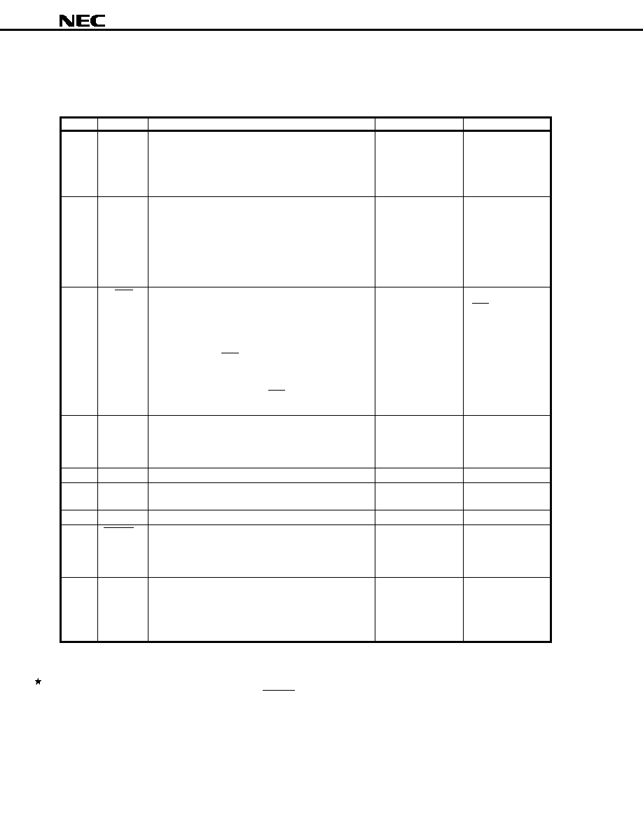
1. PIN FUNCTIONS
1.1 List of Pin Functions
Pin No.
Symbol
Function
Output Format
After Reset
1
KI/O0 to KI/O7
CMOS
High-level output
2
push-pullNote 1
15 to 20
3S0
—
High-impedance
(OFF mode)
4S1/LED
CMOS push-pull
High-level output
(LED)
5
REM
CMOS push-pull
Low-level output
6VDD
——
7XOUT
—
Low level
8XIN
(oscillation stopped)
9
GND
——
10
RESET
——
11 to 14
KI0 to KI3Note 2
—
Input (low-level)
Notes 1. Be aware that the drive capability of the low-level output side is held low.
2. In order to prevent malfunction, do not input a high level to pins KI0 to KI3 (these pins can be left open)
when reset is released (when the RESET pin changes from low level to high level, or POC is released
due to supply voltage startup).
8-bit input/output port
Input/output can be specified in 8-bit units.
In input mode, a pull-down resistor is added.
In output mode, these pins can be used as the key scan
output of the key matrix.
Input port
Can also be used as the key return input of the key
matrix.
In input mode, the use of a pull-down resistor for the S0
and S1 ports can be specified by software in 2-bit units.
If input mode is canceled by software, this pin is placed
in OFF mode and enters the high-impedance state.
Input/output port
In input mode (S1), this pin can also be used as the key
return input of the key matrix.
The use of a pull-down resistor for the S0 and S1 ports
can
be
specified
by
software in 2-bit
units.
In output mode (LED), it becomes the remote control
transmission display output (active low).
When the
remote control carrier is output from the REM output, this
pin outputs a low level from the LED output synchronously
with the REM signal.
Infrared remote control transmission output.
The output is active high.
Carrier frequency: fX/8, fX/64, fX/96, high-level, fX/16,
fX/128, fX/192 (software supporting)
Power supply
These pins are connected to system clock ceramic
resonators.
Ground
Normally, this pin is the system reset input. By inputting
a low level, the CPU can be reset. When resetting with
the POC circuit (mask option) a low level is output. A
pull-up resistor is connected to this pin.
4-bit input port
These pins can be used as the key return input of the key
matrix.
The use of a pull-down resistor can be specified by
software in 4-bit units.
相關(guān)PDF資料 |
PDF描述 |
|---|---|
| UPD703201YGC-XXX-YEU-A | 32-BIT, MROM, 20 MHz, MICROCONTROLLER, PQFP100 |
| UPD703270GF-XXX-JBT | 32-BIT, MROM, 20 MHz, RISC MICROCONTROLLER, PQFP100 |
| UPD70F3008GJ-33-8EU | 32-BIT, FLASH, 33 MHz, MICROCONTROLLER, PQFP144 |
| UPD70F3017AYF1-EA6-A | 32-BIT, FLASH, 20 MHz, MICROCONTROLLER, PBGA121 |
| UPD70F3015BGC-8EU-A | 32-BIT, FLASH, 20 MHz, MICROCONTROLLER, PQFP100 |
相關(guān)代理商/技術(shù)參數(shù) |
參數(shù)描述 |
|---|---|
| UPD62MC | 制造商:NEC 制造商全稱:NEC 功能描述:4-BIT SINGLE-CHIP MICROCONTROLLER FOR INFRARED REMOTE CONTROL TRANSMISSION |
| UPD6300C | 制造商:NEC 制造商全稱:NEC 功能描述:MOS DIGITAL INTEGRATED CIRCUIT |
| UPD6301 | 制造商:未知廠家 制造商全稱:未知廠家 功能描述:ASIC |
| UPD6307 | 制造商:NEC 制造商全稱:NEC 功能描述:UPD6307 LCD ROW DRIVER |
| UPD6307G | 制造商:NEC 制造商全稱:NEC 功能描述:UPD6307 LCD ROW DRIVER |
發(fā)布緊急采購,3分鐘左右您將得到回復(fù)。