- 您現(xiàn)在的位置:買賣IC網(wǎng) > PDF目錄383949 > TL16C552AMFN (Texas Instruments, Inc.) DUAL ASYNCHRONOUS COMMUNICATIONS ELEMENT WITH FIFO PDF資料下載
參數(shù)資料
| 型號(hào): | TL16C552AMFN |
| 廠商: | Texas Instruments, Inc. |
| 英文描述: | DUAL ASYNCHRONOUS COMMUNICATIONS ELEMENT WITH FIFO |
| 中文描述: | 雙異步通信元帶有FIFO |
| 文件頁(yè)數(shù): | 6/39頁(yè) |
| 文件大小: | 545K |
| 代理商: | TL16C552AMFN |
第1頁(yè)第2頁(yè)第3頁(yè)第4頁(yè)第5頁(yè)當(dāng)前第6頁(yè)第7頁(yè)第8頁(yè)第9頁(yè)第10頁(yè)第11頁(yè)第12頁(yè)第13頁(yè)第14頁(yè)第15頁(yè)第16頁(yè)第17頁(yè)第18頁(yè)第19頁(yè)第20頁(yè)第21頁(yè)第22頁(yè)第23頁(yè)第24頁(yè)第25頁(yè)第26頁(yè)第27頁(yè)第28頁(yè)第29頁(yè)第30頁(yè)第31頁(yè)第32頁(yè)第33頁(yè)第34頁(yè)第35頁(yè)第36頁(yè)第37頁(yè)第38頁(yè)第39頁(yè)
TL16C552A, TL16C552AM
DUAL ASYNCHRONOUS COMMUNICATIONS ELEMENT
WITH FIFO
SLLS189D – NOVEMBER 1994 – REVISED JANUARY 1999
6
POST OFFICE BOX 655303
DALLAS, TEXAS 75265
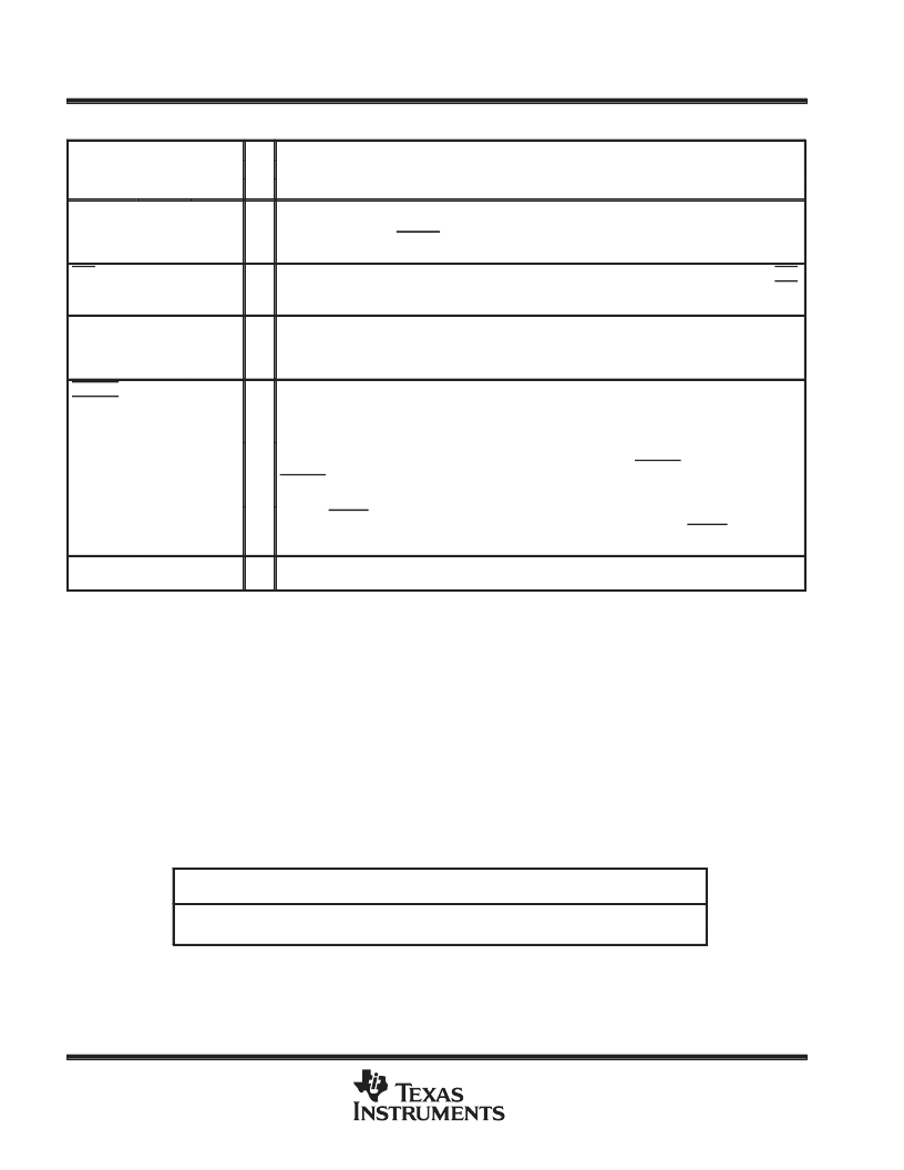
Terminal Functions (Continued)
TERMINAL
NAME
NO.
I/O
DESCRIPTION
FN
PN
39, 23
SOUT0,
SOUT1
26, 10
O
Serial data outputs. SOUT0 and SOUT1 are the serial data outputs from the ACE transmitter circuitry.
A mark is a high state and a space is a low state. Each SOUT is held in the mark condition when the
transmitter is disabled (RESET is asserted low), the transmitter register is empty, or when in the loop
mode.
STB
55
74
I/O
Line printer strobe. STB provides communication between the TL16C552A and the printer. When STB
is active (low), it provides the printer with a signal to latch the data currently on the parallel port. STB
has an internal pullup resistor to VDD of approximately 10 k
.
3-state output control input. TRI controls the 3-state control of all I/O and output terminals. When TRI
is asserted, all I/Os and outputs are in the high-impedance state, allowing board level testers to drive
the outputs without overdriving internal buffers. TRI is level sensitive and is pulled down with an internal
resistor that is approximately 5 k
.
TRI
2
12
I
TXRDY0
TXRDY1
22, 42
35, 58
O
Transmitter ready. Two types of DMA signaling are available. Either can be selected using FCR3 when
operating in FIFO mode. Only DMA mode 0 is allowed when in TL16C450 mode. Single-transfer DMA
(a transfer is made between CPU bus cycles) is supported by mode 0. Multiple transfers that are made
continuously until the transmitter FIFO has been filled are supported by mode 1.
Mode 0. In FIFO mode (FCR0 = 1, FCR3 = 0) or in TL16C450 mode (FCR0 = 0) when there are no
characters in the transmitter holding register or transmitter FIFO, TXRDYx is active (low). Once
TXRDYx is activated (low), it goes inactive after the first character is loaded into the holding register
of the transmitter FIFO.
Mode 1. TXRDY goes active (low) in FIFO mode (FCR0 = 1) when FCR3 = 1 and there are no
characters in the transmitter FIFO. When the transmitter FIFO is completely full, TXRDY goes inactive
(high).
Power supply. The VDD requirement is 5 V
±
5%.
VDD
23, 40,
64
6, 36,
56
absolute maximum ratings over operating free-air temperature range (unless otherwise noted)
Supply voltage range, V
DD
(see Note 1)
Input voltage range, V
I
Output voltage range, V
O
Continuous total power dissipation
Operating free-air temperature range, T
A:
: I suffix
–0.5 V to V
DD
+ 0.3 V
–0.5 V to 7 V
–0.5 V to V
DD
+ 0.3 V
See Dissipation Rating Table
–40
°
C to 85
°
C
–55
°
C to 125
°
C
–65
°
C to 150
°
C
. . . . . . . . . . . . . . . . . . . . . . . . . . . . . . . . . . . . . .
. . . . . . . . . . . . . . . . . . . . . . . . . . . . . . . . . . . . . . . . . . . . . . . . . . . . . . . . . . . . . .
. . . . . . . . . . . . . . . . . . . . . . . . . . . . . . . . . . . . . . . . . . . . . . . . . . .
. . . . . . . . . . . . . . . . . . . . . . . . . . . . . . . . . . . . .
. . . . . . . . . . . . . . . . . . . . . . . . . . . . . . . . . . . . .
M suffix
. . . . . . . . . . . . . . . . . . . . . . . . . . . . . . . . . . . .
Storage temperature range, T
stg
. . . . . . . . . . . . . . . . . . . . . . . . . . . . . . . . . . . . . . . . . . . . . . . . . . .
Stresses beyond those listed under “absolute maximum ratings” may cause permanent damage to the device. These are stress ratings only, and
functional operation of the device at these or any other conditions beyond those indicated under “recommended operating conditions” is not
implied. Exposure to absolute-maximum-rated conditions for extended periods may affect device reliability.
NOTE 1: All voltage levels are with respect to GND.
DISSIPATION RATING TABLE
DERATING FACTOR§
ABOVE TA = 25
°
C
19.2 mW/
°
C
13.5 mW/
°
C
PACKAGE
TA
≤
25
°
C
POWER RATING
TA = 70
°
C
POWER RATING
TA = 125
°
C
POWER RATING
FN
1730 mW
865 mW
–
HV
1689 mW
1081 mW
337 mW
Power ratings assume a maximum junction temperature (TJ) of 115
°
C for ’I’ and 150
°
C for ’M’ suffix devices.
§Derating factor is the inverse of the junction-to-ambient thermal resistance, R
θ
JA.
相關(guān)PDF資料 |
PDF描述 |
|---|---|
| TL16C554AI | ASYNCHRONOUS-COMMUNICATIONS ELEMENT |
| TL16C554I | ASYNCHRONOUS COMMUNICATIONS ELEMENT |
| TL2575-15I | 1-A SIMPLE STEP-DOWN SWITCHING VOLTAGE REGULATORS |
| TL2575-33I | 1-A SIMPLE STEP-DOWN SWITCHING VOLTAGE REGULATORS |
| TL2575_0701 | 1-A SIMPLE STEP-DOWN SWITCHING VOLTAGE REGULATORS |
相關(guān)代理商/技術(shù)參數(shù) |
參數(shù)描述 |
|---|---|
| TL16C552AMHV | 制造商:Texas Instruments 功能描述:UART 2-CH 16Byte FIFO 5V 68-Pin CFPAK Tube 制造商:Rochester Electronics LLC 功能描述:DUAL 550 UART WITH CENTRONIX PORT - Bulk |
| TL16C552AMHVB | 制造商:Texas Instruments 功能描述:5962-9755001QXA DUAL 550 UART 制造商:Texas Instruments 功能描述:UART 2-CH 16Byte FIFO 5V 68-Pin CFPAK Tube |
| TL16C552AMPN | 制造商:TI 制造商全稱:Texas Instruments 功能描述:DUAL ASYNCHRONOUS COMMUNICATIONS ELEMENT WITH FIFO |
| TL16C552APN | 功能描述:UART 接口集成電路 Dual UART w/16-Byte FIFOs & Para Port RoHS:否 制造商:Texas Instruments 通道數(shù)量:2 數(shù)據(jù)速率:3 Mbps 電源電壓-最大:3.6 V 電源電壓-最小:2.7 V 電源電流:20 mA 最大工作溫度:+ 85 C 最小工作溫度:- 40 C 封裝 / 箱體:LQFP-48 封裝:Reel |
| TL16C552APNG4 | 功能描述:UART 接口集成電路 Dual UART w/ 16-Byte FIFO RoHS:否 制造商:Texas Instruments 通道數(shù)量:2 數(shù)據(jù)速率:3 Mbps 電源電壓-最大:3.6 V 電源電壓-最小:2.7 V 電源電流:20 mA 最大工作溫度:+ 85 C 最小工作溫度:- 40 C 封裝 / 箱體:LQFP-48 封裝:Reel |
發(fā)布緊急采購(gòu),3分鐘左右您將得到回復(fù)。