- 您現(xiàn)在的位置:買賣IC網(wǎng) > PDF目錄190254 > PSD813F2-15JT (STMICROELECTRONICS) 128K X 8 FLASH, 27 I/O, PIA-GENERAL PURPOSE, PQCC52 PDF資料下載
參數(shù)資料
| 型號: | PSD813F2-15JT |
| 廠商: | STMICROELECTRONICS |
| 元件分類: | 微控制器/微處理器 |
| 英文描述: | 128K X 8 FLASH, 27 I/O, PIA-GENERAL PURPOSE, PQCC52 |
| 封裝: | PLASTIC, LCC-52 |
| 文件頁數(shù): | 62/103頁 |
| 文件大?。?/td> | 1180K |
| 代理商: | PSD813F2-15JT |
第1頁第2頁第3頁第4頁第5頁第6頁第7頁第8頁第9頁第10頁第11頁第12頁第13頁第14頁第15頁第16頁第17頁第18頁第19頁第20頁第21頁第22頁第23頁第24頁第25頁第26頁第27頁第28頁第29頁第30頁第31頁第32頁第33頁第34頁第35頁第36頁第37頁第38頁第39頁第40頁第41頁第42頁第43頁第44頁第45頁第46頁第47頁第48頁第49頁第50頁第51頁第52頁第53頁第54頁第55頁第56頁第57頁第58頁第59頁第60頁第61頁當(dāng)前第62頁第63頁第64頁第65頁第66頁第67頁第68頁第69頁第70頁第71頁第72頁第73頁第74頁第75頁第76頁第77頁第78頁第79頁第80頁第81頁第82頁第83頁第84頁第85頁第86頁第87頁第88頁第89頁第90頁第91頁第92頁第93頁第94頁第95頁第96頁第97頁第98頁第99頁第100頁第101頁第102頁第103頁
61/103
PSD8XXF2/3/4/5
PLD Power Management
The power and speed of the PLDs are controlled
by the Turbo bit (bit 3) in PMMR0. By setting the
bit to 1, the Turbo mode is off and the PLDs con-
sume the specified stand-by current when the in-
puts are not switching for an extended time of
70ns. The propagation delay time is increased by
10ns after the Turbo bit is set to 1 (turned off) when
the inputs change at a composite frequency of less
than 15 MHz. When the Turbo bit is reset to 0
(turned on), the PLDs run at full power and speed.
The Turbo bit affects the PLD’s DC power, AC
power, and propagation delay.
Blocking MCU control signals with the bits of
PMMR2 can further reduce PLD AC power con-
sumption.
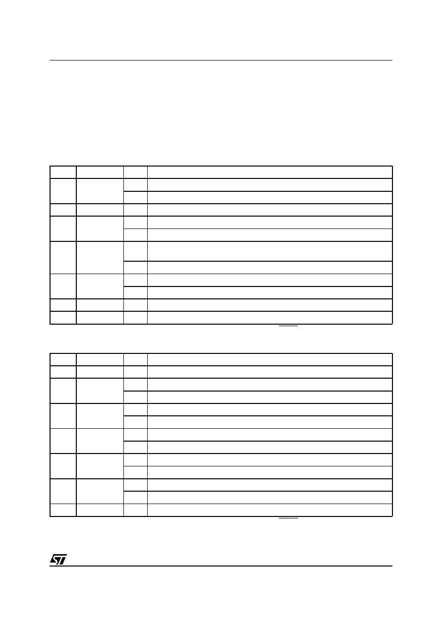
Table 30. Power Management Mode Registers PMMR0 (Note 1)
Note: 1. The bits of this register are cleared to zero following Power-up. Subsequent Reset (RESET) pulses do not clear the registers.
Table 31. Power Management Mode Registers PMMR2 (Note 1)
Note: 1. The bits of this register are cleared to zero following Power-up. Subsequent Reset (RESET) pulses do not clear the registers.
Bit 0
X
0
Not used, and should be set to zero.
Bit 1
APD Enable
0 = off Automatic Power-down (APD) is disabled.
1 = on Automatic Power-down (APD) is enabled.
Bit 2
X
0
Not used, and should be set to zero.
Bit 3
PLD Turbo
0 = on PLD Turbo mode is on
1 = off PLD Turbo mode is off, saving power.
Bit 4
PLD Array clk
0 = on
CLKIN (PD1) input to the PLD AND Array is connected. Every change of CLKIN
(PD1) Powers-up the PLD when Turbo bit is 0.
1 = off CLKIN (PD1) input to PLD AND Array is disconnected, saving power.
Bit 5
PLD MCell clk
0 = on CLKIN (PD1) input to the PLD macrocells is connected.
1 = off CLKIN (PD1) input to PLD macrocells is disconnected, saving power.
Bit 6
X
0
Not used, and should be set to zero.
Bit 7
X
0
Not used, and should be set to zero.
Bit 0
X
0
Not used, and should be set to zero.
Bit 1
X
0
Not used, and should be set to zero.
Bit 2
PLD Array
CNTL0
0 = on Cntl0 input to the PLD AND Array is connected.
1 = off Cntl0 input to PLD AND Array is disconnected, saving power.
Bit 3
PLD Array
CNTL1
0 = on Cntl1 input to the PLD AND Array is connected.
1 = off Cntl1 input to PLD AND Array is disconnected, saving power.
Bit 4
PLD Array
CNTL2
0 = on Cntl2 input to the PLD AND Array is connected.
1 = off Cntl2 input to PLD AND Array is disconnected, saving power.
Bit 5
PLD Array
ALE
0 = on ALE input to the PLD AND Array is connected.
1 = off ALE input to PLD AND Array is disconnected, saving power.
Bit 6
PLD Array
DBE
0 = on DBE input to the PLD AND Array is connected.
1 = off DBE input to PLD AND Array is disconnected, saving power.
Bit 7
X
0
Not used, and should be set to zero.
相關(guān)PDF資料 |
PDF描述 |
|---|---|
| PSD813F5V-20MT | 128K X 8 FLASH, 27 I/O, PIA-GENERAL PURPOSE, PQFP52 |
| PSD853F2-15JIT | 128K X 8 FLASH, 27 I/O, PIA-GENERAL PURPOSE, PQCC52 |
| PSD833F2-15M | 1M X 1 FLASH, 27 I/O, PIA-GENERAL PURPOSE, PQFP52 |
| PSD835G2V-B-90MI | Configurable Memory System on a Chip for 8-Bit Microcontrollers |
| PSD835G2V-B-90U | Configurable Memory System on a Chip for 8-Bit Microcontrollers |
相關(guān)代理商/技術(shù)參數(shù) |
參數(shù)描述 |
|---|---|
| PSD813F2-15M | 制造商:STMICROELECTRONICS 制造商全稱:STMicroelectronics 功能描述:Flash In-System Programmable ISP Peripherals For 8-bit MCUs |
| PSD813F2-15MI | 制造商:STMICROELECTRONICS 制造商全稱:STMicroelectronics 功能描述:Flash In-System Programmable ISP Peripherals For 8-bit MCUs |
| PSD813F2-15MIT | 制造商:STMICROELECTRONICS 制造商全稱:STMicroelectronics 功能描述:Flash In-System Programmable ISP Peripherals For 8-bit MCUs |
| PSD813F2-15MT | 制造商:STMICROELECTRONICS 制造商全稱:STMicroelectronics 功能描述:Flash In-System Programmable ISP Peripherals For 8-bit MCUs |
| PSD813F2-15U | 制造商:WSI 功能描述: 制造商:WSI 功能描述:1M X 1 FLASH, 27 I/O, PIA-GENERAL PURPOSE, PQFP64 |
發(fā)布緊急采購,3分鐘左右您將得到回復(fù)。