- 您現(xiàn)在的位置:買賣IC網(wǎng) > PDF目錄385639 > MT46V2M32LG (Micron Technology, Inc.) DOUBLE DATA RATE DDR SDRAM PDF資料下載
參數(shù)資料
| 型號(hào): | MT46V2M32LG |
| 廠商: | Micron Technology, Inc. |
| 英文描述: | DOUBLE DATA RATE DDR SDRAM |
| 中文描述: | 雙倍數(shù)據(jù)速率的DDR SDRAM內(nèi)存 |
| 文件頁數(shù): | 8/65頁 |
| 文件大?。?/td> | 2360K |
| 代理商: | MT46V2M32LG |
第1頁第2頁第3頁第4頁第5頁第6頁第7頁當(dāng)前第8頁第9頁第10頁第11頁第12頁第13頁第14頁第15頁第16頁第17頁第18頁第19頁第20頁第21頁第22頁第23頁第24頁第25頁第26頁第27頁第28頁第29頁第30頁第31頁第32頁第33頁第34頁第35頁第36頁第37頁第38頁第39頁第40頁第41頁第42頁第43頁第44頁第45頁第46頁第47頁第48頁第49頁第50頁第51頁第52頁第53頁第54頁第55頁第56頁第57頁第58頁第59頁第60頁第61頁第62頁第63頁第64頁第65頁

8
64Mb: x32 DDR SDRAM
2M32DDR-07.p65
–
Rev. 12/01
Micron Technology, Inc., reserves the right to change products or specifications without notice.
2001, Micron Technology, Inc.
64Mb: x32
DDR SDRAM
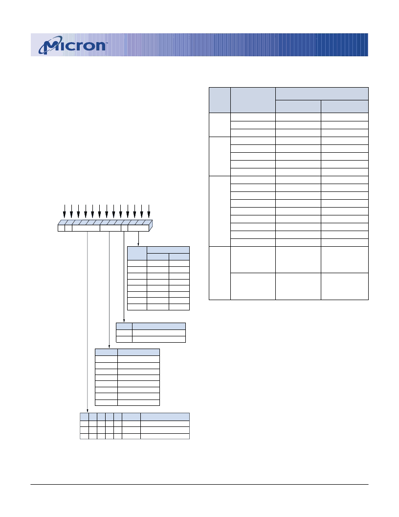
Figure 1
Mode Register Definition
M3 = 0
Reserved
2
4
8
Reserved
Reserved
Reserved
Full Page
M3 = 1
Reserved
2
4
8
Reserved
Reserved
Reserved
Full Page
Operating Mode
Normal Operation
Normal Operation/Reset DLL
All other states reserved
0
1
-
0
0
-
0
0
-
0
0
-
0
0
-
Valid
Valid
-
0
1
Burst Type
Sequential
Interleaved
CAS Latency
Reserved
Reserved
2
3
Reserved
Reserved
Reserved
Reserved
Burst Length
M0
0
1
0
1
0
1
0
1
Burst Length
CAS Latency BT
0*
0*
A9
A7 A6 A5 A4 A3
A8
A2 A1 A0
Mode Register (Mx)
Address Bus
9
7
6
5
4
3
8
2
1
0
M1
0
0
1
1
0
0
1
1
M2
0
0
0
0
1
1
1
1
M3
M4
0
1
0
1
0
1
0
1
M5
0
0
1
1
0
0
1
1
M6
0
0
0
0
1
1
1
1
M6-M0
M8
M7
Operating Mode
A10
BA1
BA0
10
11
12
* M13 and M12 (BA0 and BA1)
must be
“
0, 0
”
to select the
base mode register (vs. the
extended mode register).
M9
M10
M11
Order of Accesses Within a Burst
Burst
Length
Starting Column
Address
Type = Sequential Type = Interleaved
A0
0
1
A0
0
1
0
1
A0
0
1
0
1
0
1
0
1
2
0-1
1-0
0-1
1-0
A1
0
0
1
1
0-1-2-3
1-2-3-0
2-3-0-1
3-0-1-2
0-1-2-3
1-0-3-2
2-3-0-1
3-2-1-0
4
A2 A1
0
0
0
0
1
1
1
1
n = A0
–
A7,
A0 = 0
0
0
1
1
0
0
1
1
0-1-2-3-4-5-6-7
1-2-3-4-5-6-7-0
2-3-4-5-6-7-0-1
3-4-5-6-7-0-1-2
4-5-6-7-0-1-2-3
5-6-7-0-1-2-3-4
6-7-0-1-2-3-4-5
7-0-1-2-3-4-5-6
Cn, Cn+1, Cn+2
Cn+3, Cn+4...
…
Cn-1,
Cn
…
Cn, Cn-1, Cn-2
Cn-3, Cn-4...
…
Cn+1,
Cn
…
0-1-2-3-4-5-6-7
1-0-3-2-5-4-7-6
2-3-0-1-6-7-4-5
3-2-1-0-7-6-5-4
4-5-6-7-0-1-2-3
5-4-7-6-1-0-3-2
6-7-4-5-2-3-0-1
7-6-5-4-3-2-1-0
8
Full
Page
(256)
Not supported
n = A0
–
A7,
A0 = 1
Not supported
Table 1
Burst Definition
NOTE:
1. For a burst length of two, A1
–
A7 select the block
of two burst; A0 selects the starting column
within the block.
2. For a burst length of four, A2
–
A7 select the block
of four burst; A0
–
A1 select the starting column
within the block.
3. For a burst length of eight, A3
–
A7 select the block
of eight burst; A0
–
A2 select the starting column
within the block.
4. For a full-page burst, the full row is selected and
A0
–
A7 select the starting column. A0 also selects
the direction of the burst (incrementing if A0 = 0,
decrementing if A0 = 1).
5. Whenever a boundary of the block is reached
within a given sequence above, the following
access wraps within the block.
Reserved states should not be used, as unknown
operation or incompatibility with future versions may
result.
When a READ or WRITE command is issued, a block
of columns equal to the burst length is effectively se-
lected. All accesses for that burst take place within this
block, meaning that the burst will wrap within the block
if a boundary is reached. The block is uniquely se-
lected by A1–A
i
when the burst length is set to two, by
A2–A
i
when the burst length is set to four and by A3–A
i
when the burst length is set to eight (where A
i
is the
most significant column address bit for a given con-
figuration). The remaining (least significant) address
bit(s) is (are) used to select the starting location within
the block. The programmed burst length applies to
both READ and WRITE bursts.
相關(guān)PDF資料 |
PDF描述 |
|---|---|
| MT46V2M32V1 | DOUBLE DATA RATE DDR SDRAM |
| MT46V32M4-1 | DOUBLE DATA RATE DDR SDRAM |
| MT46V32M4TG-75 | DOUBLE DATA RATE DDR SDRAM |
| MT46V32M4TG-75L | DOUBLE DATA RATE DDR SDRAM |
| MT46V32M4TG-75Z | DOUBLE DATA RATE DDR SDRAM |
相關(guān)代理商/技術(shù)參數(shù) |
參數(shù)描述 |
|---|---|
| MT46V2M32V1 | 制造商:MICRON 制造商全稱:Micron Technology 功能描述:DOUBLE DATA RATE DDR SDRAM |
| MT46V32M16 | 制造商:Micron Technology Inc 功能描述:32MX16 DDR SDRAM PLASTIC IND TEMP BGA 2.6V DDR - Trays |
| MT46V32M16-5B | 制造商:Micron Technology Inc 功能描述: |
發(fā)布緊急采購,3分鐘左右您將得到回復(fù)。