- 您現(xiàn)在的位置:買賣IC網(wǎng) > PDF目錄385407 > HT9480 (Holtek Semiconductor Inc.) Pager Controller PDF資料下載
參數(shù)資料
| 型號: | HT9480 |
| 廠商: | Holtek Semiconductor Inc. |
| 英文描述: | Pager Controller |
| 中文描述: | 傳呼機(jī)控制器 |
| 文件頁數(shù): | 4/57頁 |
| 文件大小: | 1541K |
| 代理商: | HT9480 |
第1頁第2頁第3頁當(dāng)前第4頁第5頁第6頁第7頁第8頁第9頁第10頁第11頁第12頁第13頁第14頁第15頁第16頁第17頁第18頁第19頁第20頁第21頁第22頁第23頁第24頁第25頁第26頁第27頁第28頁第29頁第30頁第31頁第32頁第33頁第34頁第35頁第36頁第37頁第38頁第39頁第40頁第41頁第42頁第43頁第44頁第45頁第46頁第47頁第48頁第49頁第50頁第51頁第52頁第53頁第54頁第55頁第56頁第57頁

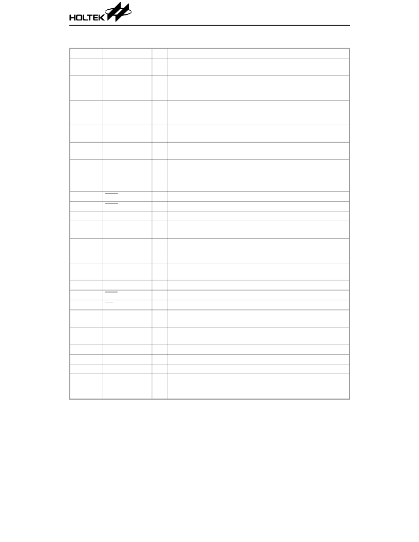
Pin Description
Pin No
Pin Name
I/O
F unction
43~49
PA0~PA6
I
7-bit input ports, with pull-high resistors
E ach bit can be configured as a wake-up input by mask option.
Bidirectional 8-bit input/output ports, pull-high mask option
T he output structures, whether tri-state or CMOS, are
determined by software instructions.
Bidirectional 2-bit input/output ports, pull-high mask option
T he output structures, whether tri-state or CMOS, are
determined by software instructions.
54~61
PB0~PB7
I/O
62~63
PC0~PC1
I/O
1, 42,
52, 64
76
77
VSS
Negative power supply (GND)
X1
X2
I
O
X1 and X2 are connected to an external crystal to form an
internal low power oscillator clock.
OSC1 and OSC2 are connected to an RC network or a crystal
(determined by mask option) to form the system clock oscillator.
For RC operation, OSC2 is the output terminal of the system
clock.
Schmitt trigger reset input, active low
Battery fail interrupt with debounce circuit input
Schmitt trigger input for timer/event counter
40
41
OSC1
OSC2
I
O
53
68
50
2, 39, 51
67
RE S
BAF
TMR1
I
I
I
VDD
Positive power supply
65
BZ
O
Buzzer non-inverting BZ output
The BZ pin outputs “high” at buzzer off (by setting the value 00H
of 1DH)
3~34
78~80
35~38
66
75
SE G31~SE G0
SE G34~SE G32
COM3~COM0
TSC
TS
O
LCD driver outputs for LCD panel segments
O
I
I
Outputs for LCD panel common connections
μ
C test mode input pin, active low with pull-high resistor
Decoder test mode input pin, active low with a pull-high resistor
Battery low indication input, active high without pull-high
resistor
POCSAG code input serial data (inverting or non-inverting as
determined by SPF32). CMOS input without pull-high resistor
Pager receiver power control enable output, CMOS output
RF dc level adjustment pin, CMOS output
PLL control pin, CMOS output
Frequency reference output pin
The FOUT output pin produces a 76.8kHz/153.6kHz signal with
a 1/2 duty cycle reference frequency if a 76.8kHz crystal is used.
69
BAL
I
70
DI
I
71
72
73
BS1
BS2
BS3
O
O
O
74
FOUT
O
HT9480
4
23th Feb ’98
相關(guān)PDF資料 |
PDF描述 |
|---|---|
| HT95168 | Caller ID Telephone IC |
| HT9580 | Character Pager Controller |
| HT95A30P | 8-Bit LCD Type Phone Controller MCU |
| HT95L300 | 8-Bit LCD Type Phone Controller MCU |
| HT95A20P | 8-Bit LCD Type Phone Controller MCU |
相關(guān)代理商/技術(shù)參數(shù) |
參數(shù)描述 |
|---|---|
| HT9480_02 | 制造商:HOLTEK 制造商全稱:Holtek Semiconductor Inc 功能描述:8-Bit Numerical Pager Controller MCU |
| HT94804 | 制造商:未知廠家 制造商全稱:未知廠家 功能描述:Numeric Pager Controller ??(Simplified Chinese Version Only) |
| HT-95 | 制造商:FCI 功能描述:RATCHET CRIMP TOOL 制造商:FCI 功能描述:RATCHET CRIMP TOOL; Crimp Size:32AWG to 22AWG; For Use With:Crimp-to-Wire PV Receptacles & Pins ;RoHS Compliant: NA |
| HT95168 | 制造商:HOLTEK 制造商全稱:Holtek Semiconductor Inc 功能描述:Caller ID Telephone IC |
| HT9580 | 制造商:HOLTEK 制造商全稱:Holtek Semiconductor Inc 功能描述:Character Pager Controller |
發(fā)布緊急采購,3分鐘左右您將得到回復(fù)。