- 您現(xiàn)在的位置:買賣IC網(wǎng) > PDF目錄199412 > TMP86CH09NG 8-BIT, MROM, 16 MHz, MICROCONTROLLER, PDIP32 PDF資料下載
參數(shù)資料
| 型號: | TMP86CH09NG |
| 元件分類: | 微控制器/微處理器 |
| 英文描述: | 8-BIT, MROM, 16 MHz, MICROCONTROLLER, PDIP32 |
| 封裝: | 0.400 INCH, 1.78 MM PITCH, LEAD FREE, PLASTIC, SDIP-32 |
| 文件頁數(shù): | 40/120頁 |
| 文件大?。?/td> | 1743K |
| 代理商: | TMP86CH09NG |
第1頁第2頁第3頁第4頁第5頁第6頁第7頁第8頁第9頁第10頁第11頁第12頁第13頁第14頁第15頁第16頁第17頁第18頁第19頁第20頁第21頁第22頁第23頁第24頁第25頁第26頁第27頁第28頁第29頁第30頁第31頁第32頁第33頁第34頁第35頁第36頁第37頁第38頁第39頁當前第40頁第41頁第42頁第43頁第44頁第45頁第46頁第47頁第48頁第49頁第50頁第51頁第52頁第53頁第54頁第55頁第56頁第57頁第58頁第59頁第60頁第61頁第62頁第63頁第64頁第65頁第66頁第67頁第68頁第69頁第70頁第71頁第72頁第73頁第74頁第75頁第76頁第77頁第78頁第79頁第80頁第81頁第82頁第83頁第84頁第85頁第86頁第87頁第88頁第89頁第90頁第91頁第92頁第93頁第94頁第95頁第96頁第97頁第98頁第99頁第100頁第101頁第102頁第103頁第104頁第105頁第106頁第107頁第108頁第109頁第110頁第111頁第112頁第113頁第114頁第115頁第116頁第117頁第118頁第119頁第120頁
Page 15
TMP86FH09ANG
Note 1: Always set RETM to “0” when transiting from NORMAL mode to STOP mode. Always set RETM to “1” when transiting
from SLOW mode to STOP mode.
Note 2: When STOP mode is released with RESET pin input, a return is made to NORMAL1 regardless of the RETM contents.
Note 3: fc: High-frequency clock [Hz], fs: Low-frequency clock [Hz], *; Don’t care
Note 4: Bits 0 and 1 in SYSCR1 are read as undefined data when a read instruction is executed.
Note 5: As the hardware becomes STOP mode under OUTEN = “0”, input value is fixed to “0”; therefore it may cause external
interrupt request on account of falling edge.
Note 6: When the key-on wakeup is used, RELM should be set to "1".
Note 7: In case of setting as STOP mode is released by a rising edge of STOP pin input, the release setting by STOP5 to STOP2
on STOPCR register is prohibited.
Note 8: Port P20 is used as STOP pin. Therefore, when stop mode is started, OUTEN does not affect to P20, and P20 becomes
High-Z mode.
Note 9: The warmig-up time should be set correctly for using oscillator.
Note 1: A reset is applied if both XEN and XTEN are cleared to “0”, XEN is cleared to “0” when SYSCK = “0”, or XTEN is cleared
to “0” when SYSCK = “1”.
Note 2: *: Don’t care, TG: Timing generator
Note 3: Bits 3, 1 and 0 in SYSCR2 are always read as undefined value.
Note 4: Do not set IDLE and TGHALT to “1” simultaneously.
Note 5: Because returning from IDLE0/SLEEP0 to NORMAL1/SLOW1 is executed by the asynchronous internal clock, the period
of IDLE0/SLEEP0 mode might be shorter than the period setting by TBTCR<TBTCK>.
Note 6: When IDLE1/2 or SLEEP1/2 mode is released, IDLE is automatically cleared to “0”.
Note 7: When IDLE0 or SLEEP0 mode is released, TGHALT is automatically cleared to “0”.
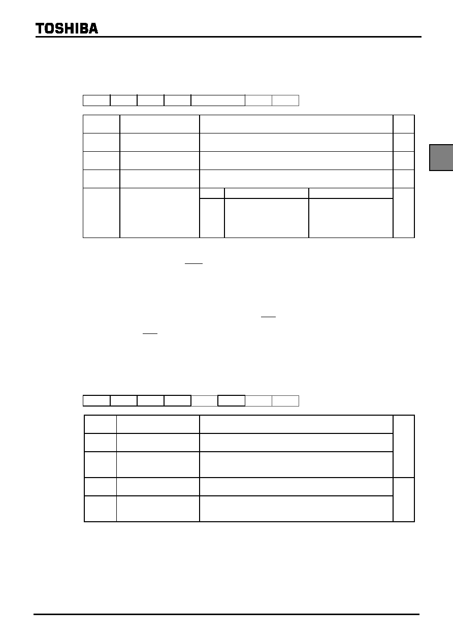
System Control Register 1
SYSCR1
76
543
21
0
(0038H)
STOP
RELM
RETM
OUTEN
WUT
(Initial value: 0000 00**)
STOP
STOP mode start
0: CPU core and peripherals remain active
1: CPU core and peripherals are halted (Start STOP mode)
R/W
RELM
Release method for STOP
mode
0: Edge-sensitive release
1: Level-sensitive release
R/W
RETM
Operating mode after STOP
mode
0: Return to NORMAL1/2 mode
1: Return to SLOW1 mode
R/W
OUTEN
Port output during STOP mode
0: High impedance
1: Output kept
R/W
WUT
Warm-up time at releasing
STOP mode
Return to NORMAL mode
Return to SLOW mode
R/W
00
01
10
11
3 x 216/fc
216/fc
3 x 214/fc
214/fc
3 x 213/fs
213/fs
3 x 26/fs
26/fs
System Control Register 2
SYSCR2
(0039H)
76
543
21
0
XEN
XTEN
SYSCK
IDLE
TGHALT
(Initial value: 1000 *0**)
XEN
High-frequency oscillator control
0: Turn off oscillation
1: Turn on oscillation
R/W
XTEN
Low-frequency oscillator control
0: Turn off oscillation
1: Turn on oscillation
SYSCK
Main system clock select
(Write)/main system clock moni-
tor (Read)
0: High-frequency clock (NORMAL1/NORMAL2/IDLE1/IDLE2)
1: Low-frequency clock (SLOW1/SLOW2/SLEEP1/SLEEP2)
IDLE
CPU and watchdog timer control
(IDLE1/2 and SLEEP1/2 modes)
0: CPU and watchdog timer remain active
1: CPU and watchdog timer are stopped (Start IDLE1/2 and SLEEP1/2 modes)
R/W
TGHALT
TG control (IDLE0 and SLEEP0
modes)
0: Feeding clock to all peripherals from TG
1: Stop feeding clock to peripherals except TBT from TG.
(Start IDLE0 and SLEEP0 modes)
相關(guān)PDF資料 |
PDF描述 |
|---|---|
| TMP86CM29BU | 8-BIT, MROM, 16 MHz, MICROCONTROLLER, PQFP64 |
| TMP86FH09NG | 8-BIT, FLASH, 16 MHz, MICROCONTROLLER, PDIP32 |
| TMP86FS49BUG | 8-BIT, FLASH, 16 MHz, MICROCONTROLLER, PQFP64 |
| TMP86PS25F | 8-BIT, OTPROM, 16 MHz, MICROCONTROLLER, PQFP100 |
| TMP87C800N | 8-BIT, MROM, 8 MHz, MICROCONTROLLER, PDIP64 |
相關(guān)代理商/技術(shù)參數(shù) |
參數(shù)描述 |
|---|---|
| TMP86CH12MG | 制造商:TOSHIBA 制造商全稱:Toshiba Semiconductor 功能描述:8 Bit Microcontroller |
| TMP86CH21AUG | 制造商:TOSHIBA 制造商全稱:Toshiba Semiconductor 功能描述:8 Bit Microcontroller |
| TMP86CH21F | 制造商:TOSHIBA 制造商全稱:Toshiba Semiconductor 功能描述:CMOS 8-Bit Microcontroller |
| TMP86CH21U | 制造商:TOSHIBA 制造商全稱:Toshiba Semiconductor 功能描述:CMOS 8-Bit Microcontroller |
| TMP86CH22UG | 制造商:TOSHIBA 制造商全稱:Toshiba Semiconductor 功能描述:8 Bit Microcontroller |
發(fā)布緊急采購,3分鐘左右您將得到回復(fù)。