- 您現(xiàn)在的位置:買賣IC網(wǎng) > PDF目錄382380 > PCD5013H (NXP SEMICONDUCTORS) FLEX roaming decoder II PDF資料下載
參數(shù)資料
| 型號: | PCD5013H |
| 廠商: | NXP SEMICONDUCTORS |
| 元件分類: | 尋呼電路 |
| 英文描述: | FLEX roaming decoder II |
| 中文描述: | TELECOM, PAGING DECODER, PQFP32 |
| 封裝: | 7 X 7 MM, 1.40 MM HEIGHT, PLASTIC, SOT-358-1, LQFP-32 |
| 文件頁數(shù): | 29/76頁 |
| 文件大小: | 270K |
| 代理商: | PCD5013H |
第1頁第2頁第3頁第4頁第5頁第6頁第7頁第8頁第9頁第10頁第11頁第12頁第13頁第14頁第15頁第16頁第17頁第18頁第19頁第20頁第21頁第22頁第23頁第24頁第25頁第26頁第27頁第28頁當前第29頁第30頁第31頁第32頁第33頁第34頁第35頁第36頁第37頁第38頁第39頁第40頁第41頁第42頁第43頁第44頁第45頁第46頁第47頁第48頁第49頁第50頁第51頁第52頁第53頁第54頁第55頁第56頁第57頁第58頁第59頁第60頁第61頁第62頁第63頁第64頁第65頁第66頁第67頁第68頁第69頁第70頁第71頁第72頁第73頁第74頁第75頁第76頁

1999 Apr 12
29
Philips Semiconductors
Product specification
FLEX
roaming decoder II
PCD5013
8.5.5
R
ECEIVER WARM
-
UP SEQUENCES
8.5.5.1
Normal receiver warm-up sequence
The PCD5013 allows for up to 6 steps associated with
warming-up the receiver. When the PCD5013 turns on the
receiver while decoding, it starts the warm-up sequence
160 ms before it requires valid signals at the EXTS1 and
EXTS0 input pins.
1.
The PCD5013 leaves the receiver control lines in the
off state for the programmed warm-up off time.
2.
The first warm-up setting, if enabled, is applied to the
receiver control lines for the amount of time
programmed for that setting.
3.
Subsequent warm-up settings are applied to the
receiver control lines for their corresponding time until
a disabled warm-up setting is found.
4.
At the end of the last used warm-up setting, the
1600 symbols per second (sps) sync setting or the
3200 sps sync setting is applied to the receiver control
lines depending on the PCD5013 current state.
The PCD5013 must be configured such that the sum of all
of the used warm-up times and the warm-up off time does
not exceed 160 ms. If it exceeds 160 ms, the PCD5013
executes the receiver shut-down sequence 160 ms after
the start of the warm-up off time. If the sum of all of the
used warm-up times and the warm-up off times is less than
160 ms, the receiver remains in the 1600 sps sync setting
or the 3200 sps sync setting from the end of the last used
warm-up setting until valid signals are expected (160 ms
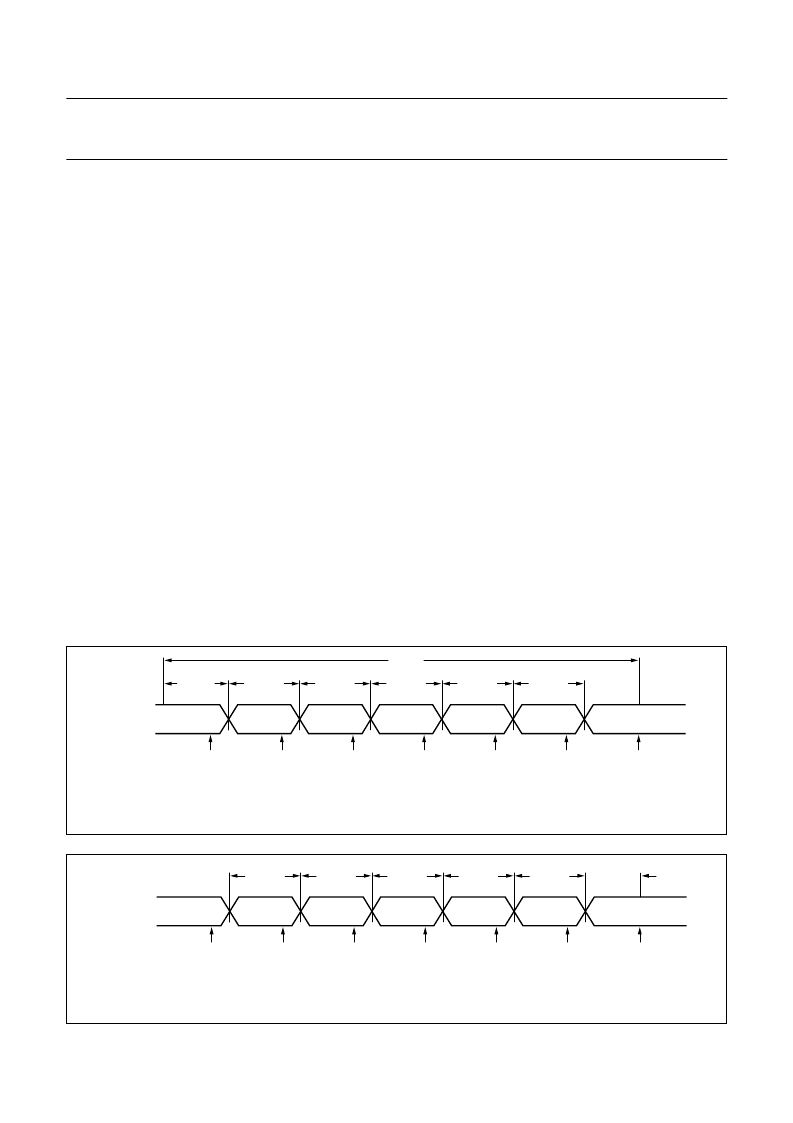
after the start of the warm-up off time). Figure 12 shows
the receiver warm-up sequence while decoding, when all
warm-up settings are enabled.
8.5.5.2
Host initiated receiver warm-up sequence
A host can initiate a receiver warm-up sequence is by one
of the following actions:
Turning on the PCD5013 by setting the ON bit in the
control packet
Requesting a noise detect by setting the SND bit in the
roaming control packet
Requesting an A-word search by setting the SAS bit in
the roaming control packet.
A host initiated receiver warm-up sequence (see Fig.13)
differs from the sequence described in Section 8.5.5.1.
No receiver warm-up off time is applied, instead the
PCD5013 immediately begins to apply the receiver
warm-up settings. Once a disabled warm-up setting is
found, the “3200 sps sync setting” (for ON and SND
warm-ups) or the “1600 sps sync setting” (for SAS
warm-ups) is applied to the receiver control lines.
The decoder then expects valid signals after the 3200 sps
sync warm-up time.
Fig.12 Receiver warm-up sequence while decoding.
handbook, full pagewidth
MGK265
receiver
control
line setting
warm-up
off time
warm-up
time 1
warm-up
setting 1
possible
LOBAT
check
off
warm-up
time 2
warm-up
setting 2
possible
LOBAT
check
possible
LOBAT
check
warm-up
time 3
160 ms
warm-up
setting 3
possible
LOBAT
check
warm-up
time 4
warm-up
setting 4
possible
LOBAT
check
warm-up
time 5
warm-up
setting 5
possible
LOBAT
check
1600 sps or 3200 sps
sync setting
EXTS1 & EXTS0
signals are expected
to be valid here
Fig.13 First receiver warm-up sequence after turning decoding on.
handbook, full pagewidth
MGK266
receiver
control
line setting
warm-up
time 1
warm-up
setting 1
possible
LOBAT
check
off
warm-up
time 2
warm-up
setting 2
possible
LOBAT
check
possible
LOBAT
check
warm-up
time 3
warm-up
setting 3
possible
LOBAT
check
warm-up
time 4
warm-up
setting 4
possible
LOBAT
check
warm-up
time 5
warm-up
setting 5
possible
LOBAT
check
3200 sps sync
warm-up
time
3200 sps
sync setting
EXTS1 & EXTS0
signals are expected
to be valid here
相關PDF資料 |
PDF描述 |
|---|---|
| PCD5032 | ADPCM CODEC for digital cordless telephones |
| PCD5032H | ADPCM CODEC for digital cordless telephones |
| PCD5032T | ADPCM CODEC for digital cordless telephones |
| PCD5041 | DECT burst mode controller |
| PCD5041H | DECT burst mode controller |
相關代理商/技術參數(shù) |
參數(shù)描述 |
|---|---|
| PCD5032 | 制造商:PHILIPS 制造商全稱:NXP Semiconductors 功能描述:ADPCM CODEC for digital cordless telephones |
| PCD5032B | 制造商:未知廠家 制造商全稱:未知廠家 功能描述:Linear CODEC |
| PCD5032D | 制造商:未知廠家 制造商全稱:未知廠家 功能描述:Linear CODEC |
| PCD5032H | 制造商:PHILIPS 制造商全稱:NXP Semiconductors 功能描述:ADPCM CODEC for digital cordless telephones |
| PCD5032T | 制造商:PHILIPS 制造商全稱:NXP Semiconductors 功能描述:ADPCM CODEC for digital cordless telephones |
發(fā)布緊急采購,3分鐘左右您將得到回復。