- 您現(xiàn)在的位置:買賣IC網(wǎng) > PDF目錄358865 > LM4560VJD (NATIONAL SEMICONDUCTOR CORP) Advanced PCI Audio Accelerator PDF資料下載
參數(shù)資料
| 型號: | LM4560VJD |
| 廠商: | NATIONAL SEMICONDUCTOR CORP |
| 元件分類: | 消費家電 |
| 英文描述: | Advanced PCI Audio Accelerator |
| 中文描述: | SPECIALTY CONSUMER CIRCUIT, PQFP100 |
| 封裝: | PLASTIC, TQFP-100 |
| 文件頁數(shù): | 5/54頁 |
| 文件大小: | 380K |
| 代理商: | LM4560VJD |
第1頁第2頁第3頁第4頁當(dāng)前第5頁第6頁第7頁第8頁第9頁第10頁第11頁第12頁第13頁第14頁第15頁第16頁第17頁第18頁第19頁第20頁第21頁第22頁第23頁第24頁第25頁第26頁第27頁第28頁第29頁第30頁第31頁第32頁第33頁第34頁第35頁第36頁第37頁第38頁第39頁第40頁第41頁第42頁第43頁第44頁第45頁第46頁第47頁第48頁第49頁第50頁第51頁第52頁第53頁第54頁
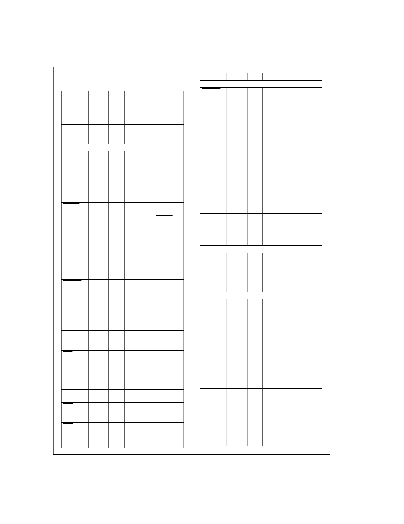
1.0 Pin Description
(Continued)
1.2 PIN DESCRIPTION
Symbol
V
DD
Pin(s)
20, 39,
52, 53,
69, 83,
100
11, 30,
48, 60,
75, 90
Type
IN
Description
3.3V Power Supply
V
SS
IN
Ground
PCI BUS INTERFACE SIGNALS (51)
AD[31:0]
92–99,
3–10,
21–28,
31–38
C/BE[3:0]
1, 12,
19, 29
I/O
PCI Address/Data Bus.
A time-multiplexed
address data bus.
I/O
PCI Command/Byte
Enable.
Defines the type
of AD bus transaction
type.
Cycle Frame.
A PCI
transaction begins and
ends with the FRAME
signal.
Initiator Ready.
An active
low indicates the cycle
initiator is ready to send
or receive data.
Target Ready.
An active
low indicates that the
target is read to complete
the current transaction.
Device Select.
An active
low indicates the target
has decoded its address.
STOP.
An active low
indicates the target wants
the initiator to stop data
during the current data
phase.
Parity.
Generates an
even parity for the
AD[31.0].
Reset.
A low active signal
which resets the PCI
device.
Interrupt.
An active low
signals in interrupt to the
CPU.
Clock.
The clock that
drives the PCI timing.
Grant.
An active low
signals the master has
access to the PCI bus.
Request.
An active low
indicates the master
wants access to the PCI
bus.
FRAME
13
I/O
IRDY
14
I/O
TRDY
15
I/O
DEVSEL
16
I/O
STOP
17
I/O
PAR
18
I/O
RST
86
IN
INT
84
OUT
PCICLK
87
IN
GNT
88
IN
REQ
89
OUT
Symbol
PCI BUS INTERFACE SIGNALS (51)
CLKRUN
85
Pin(s)
Type
Description
I/O
Clock Run.
An active low
signal used for power
management on
motherboards only. It is
not assigned a pin on the
PCI connector.
Power Management
Event.
An active low
signal used for power
management for add in
cards or motherboards. It
is assigned a pin on the
PCI connector.
Terminal Count.
This
input is asserted by the
DMA controller to indicate
the end of a DMA
transfer. The signal is
only effective during a
DMA access cycle.
Initialization Device
Select.
An active high
allows reads to the PCI
devices configuration
registers.
PME
91
OUT
TC
78
IN
IDSEL
2
IN
MPU-401 INTERFACE SIGNALS (2)
MIDIOUT
50
OUT
MIDI Data Out.
Sends
midi data to the midi
connector.
MIDI Data In.
Receives
midi data from an
optocoupler.
MIDIIN
49
IN
AC97 CODEC INTERFACE SIGNALS (6)
ACRST
57
OUT
AC97 Master Reset.
An
active low which resets
the internal circuitry of
AC97 codecs.
AC97 Bit Clock.
A
12.288 MHz clock from
the codec. This is used to
synchronize the data
streams to and from the
codecs.
AC97 Sync.
Used to start
the data frame used to
format the serial data to
and from the codecs.
Primary CODEC Serial
Data Input.
This receives
serial data in from the
primary codec.
Secondary CODEC
Serial Data Input.
This
receives serial data in
from the secondary
codec.
ACCLK
55
IN
ACSYNC
56
I/O
ACDI1
58
IN
ACDI2
59
IN
www.national.com
5
相關(guān)PDF資料 |
PDF描述 |
|---|---|
| LM4560 | Advanced PCI Audio Accelerator |
| LM45BIM3 | SOT-23 Precision Centigrade Temperature Sensors |
| LM45BIM3X | SOT-23 Precision Centigrade Temperature Sensors |
| LM45B | SOT-23 Precision Centigrade Temperature Sensors |
| LM4610 | Dual DC Operated Tone/Volume/Balance Circuit with National 3-D Sound |
相關(guān)代理商/技術(shù)參數(shù) |
參數(shù)描述 |
|---|---|
| LM4562 | 制造商:NSC 制造商全稱:National Semiconductor 功能描述:Dual High Performance, High Fidelity Audio Operational Amplifier |
| LM4562_07 | 制造商:NSC 制造商全稱:National Semiconductor 功能描述:Dual High Performance, High Fidelity Audio Operational Amplifier |
| LM4562HA | 制造商:Texas Instruments 功能描述:OP Amp Dual GP ??17V 8-Pin TO-99 Tray |
| LM4562HA/NOPB | 功能描述:運算放大器 - 運放 RoHS:否 制造商:STMicroelectronics 通道數(shù)量:4 共模抑制比(最小值):63 dB 輸入補償電壓:1 mV 輸入偏流(最大值):10 pA 工作電源電壓:2.7 V to 5.5 V 安裝風(fēng)格:SMD/SMT 封裝 / 箱體:QFN-16 轉(zhuǎn)換速度:0.89 V/us 關(guān)閉:No 輸出電流:55 mA 最大工作溫度:+ 125 C 封裝:Reel |
| LM4562HA/NOPB | 制造商:Texas Instruments 功能描述:Operational Amplifier (Op-Amp) IC |
發(fā)布緊急采購,3分鐘左右您將得到回復(fù)。