- 您現(xiàn)在的位置:買賣IC網(wǎng) > PDF目錄98069 > S1D13A05B00B 320 X 320 PIXELS CRT OR FLAT PNL GRPH DSPL CTLR, PBGA121 PDF資料下載
參數(shù)資料
| 型號: | S1D13A05B00B |
| 元件分類: | 顯示控制器 |
| 英文描述: | 320 X 320 PIXELS CRT OR FLAT PNL GRPH DSPL CTLR, PBGA121 |
| 封裝: | PLASTIC, FBGA-121 |
| 文件頁數(shù): | 190/190頁 |
| 文件大小: | 2285K |
| 代理商: | S1D13A05B00B |
第1頁第2頁第3頁第4頁第5頁第6頁第7頁第8頁第9頁第10頁第11頁第12頁第13頁第14頁第15頁第16頁第17頁第18頁第19頁第20頁第21頁第22頁第23頁第24頁第25頁第26頁第27頁第28頁第29頁第30頁第31頁第32頁第33頁第34頁第35頁第36頁第37頁第38頁第39頁第40頁第41頁第42頁第43頁第44頁第45頁第46頁第47頁第48頁第49頁第50頁第51頁第52頁第53頁第54頁第55頁第56頁第57頁第58頁第59頁第60頁第61頁第62頁第63頁第64頁第65頁第66頁第67頁第68頁第69頁第70頁第71頁第72頁第73頁第74頁第75頁第76頁第77頁第78頁第79頁第80頁第81頁第82頁第83頁第84頁第85頁第86頁第87頁第88頁第89頁第90頁第91頁第92頁第93頁第94頁第95頁第96頁第97頁第98頁第99頁第100頁第101頁第102頁第103頁第104頁第105頁第106頁第107頁第108頁第109頁第110頁第111頁第112頁第113頁第114頁第115頁第116頁第117頁第118頁第119頁第120頁第121頁第122頁第123頁第124頁第125頁第126頁第127頁第128頁第129頁第130頁第131頁第132頁第133頁第134頁第135頁第136頁第137頁第138頁第139頁第140頁第141頁第142頁第143頁第144頁第145頁第146頁第147頁第148頁第149頁第150頁第151頁第152頁第153頁第154頁第155頁第156頁第157頁第158頁第159頁第160頁第161頁第162頁第163頁第164頁第165頁第166頁第167頁第168頁第169頁第170頁第171頁第172頁第173頁第174頁第175頁第176頁第177頁第178頁第179頁第180頁第181頁第182頁第183頁第184頁第185頁第186頁第187頁第188頁第189頁當(dāng)前第190頁

Epson Research and Development
Page 99
Vancouver Design Center
Hardware Functional Specification
S1D13A05
Issue Date: 02/07/02
X40A-A-001-02
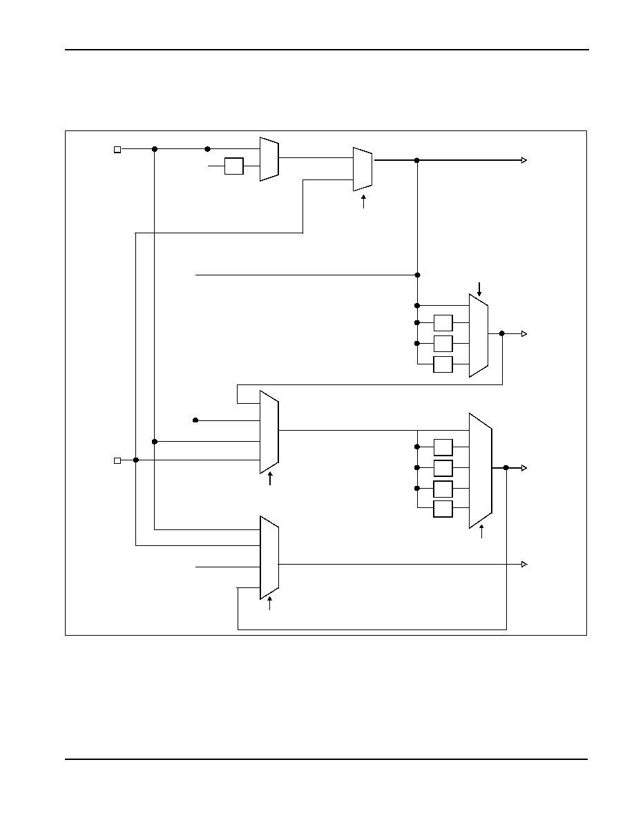
7.2 Clock Selection
The following diagram provides a logical representation of the S1D13A05 internal clocks
used for the LCD controller.
Figure 7-1: Clock Selection
Note
1 CNF6 must be set at RESET#.
CLKI
CLKI2
÷2
0
1
BCLK
÷2
÷3
÷4
00
01
10
11
MCLK
00
01
10
11
÷2
÷3
÷4
000
001
010
011
÷8
1xx
PCLK
PWMCLK
REG[08h] bits 1,0
REG[70h] bits 2-1
REG[08h] bits 6-4
REG[04h] bits 5-4
CNF61
00
01
10
11
0
1
REG[04h] bit 0
相關(guān)PDF資料 |
PDF描述 |
|---|---|
| S1D13A05F00A100 | 320 X 320 PIXELS CRT OR FLAT PNL GRPH DSPL CTLR, PBGA121 |
| S1R72005F00A300 | UNIVERSAL SERIAL BUS CONTROLLER, PQFP64 |
| S1R72105F00A000 | SCSI BUS CONTROLLER, PQFP100 |
| S1R72803F00A100 | 1 CHANNEL(S), 400M bps, SERIAL COMM CONTROLLER, PQFP100 |
| S1R72C05B08 | UNIVERSAL SERIAL BUS CONTROLLER, PBGA121 |
相關(guān)代理商/技術(shù)參數(shù) |
參數(shù)描述 |
|---|---|
| S1D13A05B00B200 | 功能描述:LCD 驅(qū)動器 (QVGA) 320x240 LCD Controller @ 16bpp RoHS:否 制造商:Maxim Integrated 數(shù)位數(shù)量:4.5 片段數(shù)量:30 最大時鐘頻率:19 KHz 工作電源電壓:3 V to 3.6 V 最大工作溫度:+ 85 C 最小工作溫度:- 20 C 封裝 / 箱體:PDIP-40 封裝:Tube |
| S1D13A05F00A100 | 功能描述:顯示驅(qū)動器和控制器 (QVGA) 320x240 LCD Controller @ 16bpp RoHS:否 制造商:Panasonic Electronic Components 工作電源電壓:2.7 V to 5.5 V 最大工作溫度: 安裝風(fēng)格:SMD/SMT 封裝 / 箱體:QFN-44 封裝:Reel |
| S1D13A05F00A200 | 制造商:Epson Electronics America Inc 功能描述:LCD DRVR 3V/3.3V/5V 80-Pin TQFP |
| S1D-13-F | 功能描述:整流器 200V 1A RoHS:否 制造商:Vishay Semiconductors 產(chǎn)品:Standard Recovery Rectifiers 配置: 反向電壓:100 V 正向電壓下降: 恢復(fù)時間:1.2 us 正向連續(xù)電流:2 A 最大浪涌電流:35 A 反向電流 IR:5 uA 安裝風(fēng)格:SMD/SMT 封裝 / 箱體:DO-221AC 封裝:Reel |
| S1D13T03F10A100 | 制造商:Epson Electronics America Inc 功能描述:IC EPD CONTROLLER 64TQFP13 制造商:Epson Electronics America Inc 功能描述:EPD Controller Timing control |
發(fā)布緊急采購,3分鐘左右您將得到回復(fù)。