- 您現(xiàn)在的位置:買賣IC網(wǎng) > PDF目錄4578 > IDT88P8344BHGI (IDT, Integrated Device Technology Inc)IC SPI3-SPI4 EXCHANGE 820-PBGA PDF資料下載
參數(shù)資料
| 型號: | IDT88P8344BHGI |
| 廠商: | IDT, Integrated Device Technology Inc |
| 文件頁數(shù): | 28/98頁 |
| 文件大小: | 0K |
| 描述: | IC SPI3-SPI4 EXCHANGE 820-PBGA |
| 標(biāo)準(zhǔn)包裝: | 24 |
| 系列: | * |
| 其它名稱: | 88P8344BHGI |
第1頁第2頁第3頁第4頁第5頁第6頁第7頁第8頁第9頁第10頁第11頁第12頁第13頁第14頁第15頁第16頁第17頁第18頁第19頁第20頁第21頁第22頁第23頁第24頁第25頁第26頁第27頁當(dāng)前第28頁第29頁第30頁第31頁第32頁第33頁第34頁第35頁第36頁第37頁第38頁第39頁第40頁第41頁第42頁第43頁第44頁第45頁第46頁第47頁第48頁第49頁第50頁第51頁第52頁第53頁第54頁第55頁第56頁第57頁第58頁第59頁第60頁第61頁第62頁第63頁第64頁第65頁第66頁第67頁第68頁第69頁第70頁第71頁第72頁第73頁第74頁第75頁第76頁第77頁第78頁第79頁第80頁第81頁第82頁第83頁第84頁第85頁第86頁第87頁第88頁第89頁第90頁第91頁第92頁第93頁第94頁第95頁第96頁第97頁第98頁

34
IDT88P8344 SPI EXCHANGE 4 x SPI-3 TO SPI-4
INDUSTRIALTEMPERATURERANGE
APRIL 10, 2006
4.4 Microprocessor interface to SPI-3 datapath
capture/insert configurable parameters
Enable insertion / capture of data to the SPI-3 or SPI-4 data stream (which
is dependent on the egress control register). For each direction, the following
are to be used:
- Data for insertion or data captured
- Data available: set when data is available. Asserted by device for capture,
asserted by microprocessor for insertion.
- LID: Logical Identifier of capture / insertion channel
- Length: length of data for insertion or capture
- Flags: SOP, EOP, address parity error, data parity error, packet error
Thereareseparateinstantiationsofmicroprocessorinsertcapturebuffersfor
SPI-3 and SPI-4.
Capture data fragment
Packets can be captured from the SPI-3-4 stream and directed towards the
microprocessor. The capture buffer can store only one 256 byte packet
fragment. When the buffer is full the DATA_AVAILABLE flag is set and a SPI-
3captureeventisgenerated.Theeventisdirectedtowardstheinterruptmodule.
Read packet data fragment
The microprocessor needs to read a buffer to capture a packet fragment. It
verifies the DATA_AVAILABLE flag in the SPI-3 capture control register.
Microprocessor reads the packet fragment and EOP, SOP, ERROR, LID and
LENGTHfieldsfromtheSPI-3datacapturebuffer.Microprocessorhandsover
controlofthecapturebufferwhenitclearstheDATA_AVAILABLEflagintheSPI-
3 data capture control register (Table 31 - SPI-3 data capture control register).
4.4.1 SPI-3 to ingress microprocessor interface
datapath
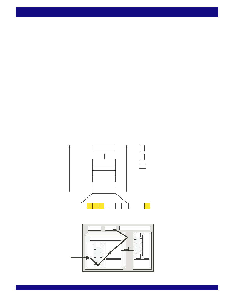
The diagram below shows the datapath through the device from the SPI-3
interface to the microprocessor capture interface.
The following is a description of the path taken by a fragment of data through
the device.
DataentersonaSPI-3interfaceinfragments.Fragmentsareofequallength
except the last fragment of a packet which may be shorter. The LP address is
in-band with the data. The fragment enters a SPI-3 ingress buffer. SPI-3 LP
address, error information, SOP, and EOP are stored with the fragment. The
LP address is mapped to a LID. The fragment is stored in LID allocated buffer
segments.
The Table 80, SPI-3 egress port descriptor table (64 entries) is consulted,
and the PFP decides to send this LID to the microprocessor capture port. Data
ismovedtothecapturebufferalongwiththeLPaddress.LID,errorinformation,
SOP, and EOP. The data available bit is set. Data and control information are
read from the relevant register space through the microprocessor interface.
Figure 23. SPI-3 ingress to microprocessor capture interface datapath
…
JTAG
uproc
Chip Counters Memory
4 x SPI-3
8 bit / 32 bit
Min: 19.44MHz
Max: 133MHz
SPI-4.2
Min: 80 MHz
Max: 400 MHz
Interf
ace
Bloc
k
Interf
ace
Bloc
k
SPI-3 /
LID map
SPI-4 /
LID map
Main
Memory
A
LID Counters Memory
6370 drw15
Figure 22 . Microprocessor data capture buffer
6370 drw28
flags
length
data[1]
data[2]
data[255]
lid
data[0]
SOP
EA
ED
PAR
EOP
not used
EA
ED
PAR
data parity error
address parity error
packet error
70
inser
tsequence
t
t+1
t+258
e
xtr
act
sequence
t
t+1
t+258
相關(guān)PDF資料 |
PDF描述 |
|---|---|
| ESM44DRAS | CONN EDGECARD 88POS R/A .156 SLD |
| ASM28DSAS | CONN EDGECARD 56POS R/A .156 SLD |
| ESC60DRTN-S93 | CONN EDGECARD 120PS DIP .100 SLD |
| ESC60DRTH-S93 | CONN EDGECARD 120PS DIP .100 SLD |
| MIC5232-3.3YML TR | IC REG LDO 3.3V 10MA 6-MLF |
相關(guān)代理商/技術(shù)參數(shù) |
參數(shù)描述 |
|---|---|
| IDT88P8344BHI | 功能描述:IC SPI3-SPI4 EXCHANGE 820-PBGA RoHS:否 類別:集成電路 (IC) >> 專用 IC 系列:* 產(chǎn)品培訓(xùn)模塊:Lead (SnPb) Finish for COTS Obsolescence Mitigation Program 標(biāo)準(zhǔn)包裝:1 系列:- 類型:調(diào)幀器 應(yīng)用:數(shù)據(jù)傳輸 安裝類型:表面貼裝 封裝/外殼:400-BBGA 供應(yīng)商設(shè)備封裝:400-PBGA(27x27) 包裝:散裝 |
| IDT89H10T4BG2ZBBC | 制造商:Integrated Device Technology Inc 功能描述:IC PCI SW 10LANE 4PORT 324BGA |
| IDT89H10T4BG2ZBBC8 | 制造商:Integrated Device Technology Inc 功能描述:IC PCI SW 10LANE 4PORT 324BGA |
| IDT89H10T4BG2ZBBCG | 功能描述:IC PCI SW 10LANE 4PORT 324BGA RoHS:是 類別:集成電路 (IC) >> 專用 IC 系列:PRECISE™ 產(chǎn)品培訓(xùn)模塊:Lead (SnPb) Finish for COTS Obsolescence Mitigation Program 標(biāo)準(zhǔn)包裝:1 系列:- 類型:調(diào)幀器 應(yīng)用:數(shù)據(jù)傳輸 安裝類型:表面貼裝 封裝/外殼:400-BBGA 供應(yīng)商設(shè)備封裝:400-PBGA(27x27) 包裝:散裝 |
| IDT89H10T4BG2ZBBCG8 | 制造商:Integrated Device Technology Inc 功能描述:IC PCI SW 10LANE 4PORT 324BGA |
發(fā)布緊急采購,3分鐘左右您將得到回復(fù)。