- 您現(xiàn)在的位置:買賣IC網(wǎng) > PDF目錄385403 > HT82A850R (Holtek Semiconductor Inc.) Audio MCU PDF資料下載
參數(shù)資料
| 型號: | HT82A850R |
| 廠商: | Holtek Semiconductor Inc. |
| 英文描述: | Audio MCU |
| 中文描述: | 音頻控制器 |
| 文件頁數(shù): | 11/41頁 |
| 文件大小: | 296K |
| 代理商: | HT82A850R |
第1頁第2頁第3頁第4頁第5頁第6頁第7頁第8頁第9頁第10頁當前第11頁第12頁第13頁第14頁第15頁第16頁第17頁第18頁第19頁第20頁第21頁第22頁第23頁第24頁第25頁第26頁第27頁第28頁第29頁第30頁第31頁第32頁第33頁第34頁第35頁第36頁第37頁第38頁第39頁第40頁第41頁
HT82A850R
Rev. 1.10
11
July 25, 2007
During the execution of an interrupt subroutine, other in-
terrupt acknowledge signals are held until the RETI in-
struction is executed or the EMI bit and the related
interrupt control bit are set to 1 (if the stack is not full). To
return from the interrupt subroutine, a RET or RETI
instruction should be executed. A RETI instruction will
set the EMI bit to enable an interrupt service, but a RET
instruction will not.
Interrupts, occurring in the interval between the rising
edges of two consecutive T2 pulses, will be serviced on
the latter of the two T2 pulses, if the corresponding inter-
rupts are enabled. In the case of simultaneous requests
the following table shows the priority that is applied.
These can be masked by resetting the EMI bit.
Interrupt Source
Priority
Vector
Reserved
1
04H
Timer/Event Counter 0 overflow
2
08H
Timer/Event Counter 1 overflow
3
0CH
Play Interrupt
4
10H
Serial Interface Interrupt
5
14H
Record Interrupt
6
18H
It is recommended that a program does not use the
CALL subroutine within the interrupt subroutine. Inter-
rupts often occur in an unpredictable manner or need to
be serviced immediately in some applications. If only one
stack is left and enabling the interrupt is not well con-
trolled, the original control sequence will be damaged
once the CALL operates in the interrupt subroutine.
Oscillator Configuration
An internal oscillator circuit is integrated within the
microcontroller to implement the system clock. When
the device enters the Power-down mode the system os-
cillator will stop running and external signals will be
ignored to conserve power.
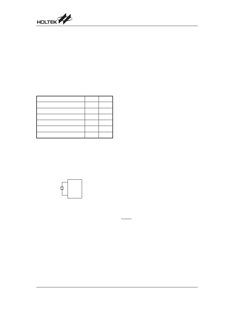
A crystal across OSCI and OSCO is required to provide
the feedback and phase shift required for the oscillator.
No other external components are required. Instead of a
crystal, a resonator can also be connected between
OSCI and OSCO to obtain the correct frequency refer-
ence, however two external capacitors between the
OSCI, OSCO pins and ground are required.
A WDT oscillator is also contained within the device.
This is a free running fully integrated RC oscillator
requiring no external components. Even if the system
enters the power down mode, where the system clock is
stopped, the WDT oscillator continues to run. The WDT
oscillator can be disabled by a configuration option to
conserve power.
Watchdog Timer
WDT
The WDT clock source is implemented by its own dedi-
cated internal RC oscillator (WDT oscillator) or by using
the instruction clock, which is the system clock/4. The
WDT timer is designed to prevent a software malfunc-
tion or sequence from jumping to an unknown location
with unpredictable results. The WDT can be disabled
using a configuration option. Note that if the WDT is dis-
abled, all executions of instructions related to the WDT
will result in no operation.
When the WDTclock source is selected, it will be first di-
vided by 256 (8-stage) to obtain a nominal time-out pe-
riod. By using this WDT prescaler, longer time-out
periods can be implemented. This is achieved by writing
data to the the WS2, WS1, WS0 bits.
The WDT OSC period has a typical value of 65 s. This
time-out period may vary with temperature, VDD and
process variations. The WDTOSC keeps running in any
operational mode.
If the instruction clock is selected as the WDT clock
source, the WDT operates in the same manner except
when the device is in the Power-down mode. Here the
WDT stops counting and loses its protecting function. In
this situation the device can only be re-started by exter-
nal logic. The high nibble and bit3 of the WDTS are re-
served for user defined flags, which can be used to
indicate some specified status.
The WDT overflow under normal operation initialises a
chip reset
and sets the status bit
TO . In the
Power-down mode, the overflow initialises a warm re-
set , where only the PC and SP are reset to zero. To
clear the contents of the WDT, there are three methods
that can be used, i.e., external reset (a low level on the
RESET pin), a software instruction, and a HALT in-
struction. There are two types of software instructions;
CLR WDT and the other set CLR WDT1 and CLR
WDT2 . Of these two types of instruction, only one type
of instruction can be active at a time depending on the
options CLR WDT times selection option. If the CLR
WDT is selected (i.e., CLR WDT times equal one), any
execution of the CLR WDT instruction clears the WDT.
In the case that CLR WDT1 and CLR WDT2 are
chosen (i.e., CLR WDT times equal two), these two in-
structions have to be executed to clear the WDT; other-
wise, the WDT may reset the chip due to time-out.
& %
& &
System Oscillator
相關PDF資料 |
PDF描述 |
|---|---|
| HT82A851R | USB Audio MCU |
| HT82J30A | 16 Channel A/D MCU with SPI Interface |
| HT82J30R | 16 Channel A/D MCU with SPI Interface |
| HT82J927A | USB Gamepad |
| HT82J97E | USB Joystick Encoder 8-Bit OTP MCU |
相關代理商/技術參數(shù) |
參數(shù)描述 |
|---|---|
| HT82A851R | 制造商:HOLTEK 制造商全稱:Holtek Semiconductor Inc 功能描述:USB Audio MCU |
| HT82B40A | 制造商:HOLTEK 制造商全稱:Holtek Semiconductor Inc 功能描述:I/O MCU with USB Interface |
| HT82B40R | 制造商:HOLTEK 制造商全稱:Holtek Semiconductor Inc 功能描述:I/O MCU with USB Interface |
| HT82B40R_11 | 制造商:HOLTEK 制造商全稱:Holtek Semiconductor Inc 功能描述:I/O MCU with USB Interface |
| HT82B42R | 制造商:HOLTEK 制造商全稱:Holtek Semiconductor Inc 功能描述:I/O MCU with USB Interface |
發(fā)布緊急采購,3分鐘左右您將得到回復。