- 您現(xiàn)在的位置:買(mǎi)賣(mài)IC網(wǎng) > PDF目錄10218 > CS8416-CNZ (Cirrus Logic Inc)IC RCVR DGTL 192KHZ 28QFN COMM PDF資料下載
參數(shù)資料
| 型號(hào): | CS8416-CNZ |
| 廠商: | Cirrus Logic Inc |
| 文件頁(yè)數(shù): | 2/37頁(yè) |
| 文件大小: | 0K |
| 描述: | IC RCVR DGTL 192KHZ 28QFN COMM |
| 標(biāo)準(zhǔn)包裝: | 490 |
| 類(lèi)型: | 數(shù)字音頻接口接收器 |
| 應(yīng)用: | 數(shù)字音頻 |
| 安裝類(lèi)型: | 表面貼裝 |
| 封裝/外殼: | 28-QFN |
| 供應(yīng)商設(shè)備封裝: | 28-QFN 裸露焊盤(pán)(5x5) |
| 包裝: | 管件 |
| 產(chǎn)品目錄頁(yè)面: | 759 (CN2011-ZH PDF) |
| 配用: | 598-1017-ND - BOARD EVAL FOR CS8416 RCVR |
| 其它名稱: | 598-1723 |
第1頁(yè)當(dāng)前第2頁(yè)第3頁(yè)第4頁(yè)第5頁(yè)第6頁(yè)第7頁(yè)第8頁(yè)第9頁(yè)第10頁(yè)第11頁(yè)第12頁(yè)第13頁(yè)第14頁(yè)第15頁(yè)第16頁(yè)第17頁(yè)第18頁(yè)第19頁(yè)第20頁(yè)第21頁(yè)第22頁(yè)第23頁(yè)第24頁(yè)第25頁(yè)第26頁(yè)第27頁(yè)第28頁(yè)第29頁(yè)第30頁(yè)第31頁(yè)第32頁(yè)第33頁(yè)第34頁(yè)第35頁(yè)第36頁(yè)第37頁(yè)
10
DS578F3
CS8416
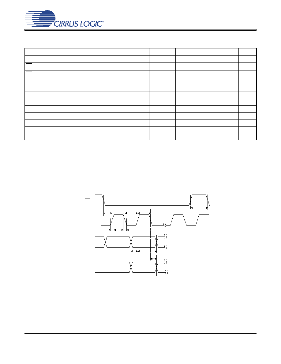
SWITCHING CHARACTERISTICS - CONTROL PORT - SPI MODE
(Inputs: Logic 0 = 0 V, Logic 1 = VL; CL = 20 pF)
Notes:
12. If Fs is lower than 46.875 kHz, the maximum CCLK frequency should be less than 128 Fs. This is dic-
tated by the timing requirements necessary to access the Channel Status memory. Access to the con-
trol register file can be carried out at the full 6 MHz rate. The minimum allowable input sample rate is
32 kHz, so choosing CCLK to be less than or equal to 4.1 MHz should be safe for all possible conditions.
13. Data must be held for sufficient time to bridge the transition time of CCLK.
14. For fsck <1 MHz.
Parameter
Symbol
Min
Max
Unit
CCLK Clock Frequency
fsck
06.0
MHz
CS High Time Between Transmissions
tcsh
1.0
-
s
CS Falling to CCLK Edge
tcss
20
-
ns
CCLK Low Time
tscl
66
-
ns
CCLK High Time
tsch
66
-
ns
CDIN to CCLK Rising Setup Time
tdsu
40
-
ns
CCLK Rising to DATA Hold Time
tdh
15
-
ns
CCLK Falling to CDOUT Stable
tpd
-50
ns
Rise Time of CDOUT
tr1
-25
ns
Fall Time of CDOUT
tf1
-25
ns
Rise Time of CCLK and CDIN
tr2
-100
ns
Fall Time of CCLK and CDIN
tr2
-100
ns
t r2
t f2
t dsu
t dh
t sch
t scl
CS
CCLK
CDIN
t css
t pd
CDOUT
t csh
Figure 3. SPI Mode Timing
相關(guān)PDF資料 |
PDF描述 |
|---|---|
| VI-21J-IU-F2 | CONVERTER MOD DC/DC 36V 200W |
| SP3494EN-L/TR | IC TXRX RS485/RS422 LP 8NSOIC |
| SP3491EN-L/TR | IC TXRX RS485 FULL DUPLX 14NSOIC |
| AD7828BRZ-REEL | IC ADC 8BIT 8CHAN HS 28SOIC |
| AD7472BRZ | IC ADC 12BIT PARALLEL 24SOIC |
相關(guān)代理商/技術(shù)參數(shù) |
參數(shù)描述 |
|---|---|
| CS8416-CNZ | 制造商:Cirrus Logic 功能描述:Receiver IC RoHS Compliant:Yes |
| CS8416-CNZR | 功能描述:音頻發(fā)送器、接收器、收發(fā)器 IC 192 kHz Digital Audio Receiver RoHS:否 制造商:Cirrus Logic 工作電源電壓:3.3 V, 5 V 電源電流:11.8 mA 通道數(shù)量:1 最大工作溫度:+ 70 C 接口類(lèi)型:I2C, SPI 安裝風(fēng)格:SMD/SMT 封裝 / 箱體:TSSOP-28 封裝: |
| CS8416-CS | 制造商:CIRRUS 制造商全稱:Cirrus Logic 功能描述:192 kHZ DIGITAL AUDIO INTERFACE RECEIVER |
| CS8416-CSR | 制造商:Cirrus Logic 功能描述:- Tape and Reel |
| CS8416CSZ | 制造商:Cirrus Logic 功能描述: |
發(fā)布緊急采購(gòu),3分鐘左右您將得到回復(fù)。