- 您現(xiàn)在的位置:買(mǎi)賣(mài)IC網(wǎng) > PDF目錄374047 > ADV7303AKST (ANALOG DEVICES INC) Sand Paper; Abrasive Grade:T; Color:White; Pack Quantity:3; Roll Length:30ft; Width:4" PDF資料下載
參數(shù)資料
| 型號(hào): | ADV7303AKST |
| 廠(chǎng)商: | ANALOG DEVICES INC |
| 元件分類(lèi): | 顏色信號(hào)轉(zhuǎn)換 |
| 英文描述: | Sand Paper; Abrasive Grade:T; Color:White; Pack Quantity:3; Roll Length:30ft; Width:4" |
| 中文描述: | COLOR SIGNAL ENCODER, PQFP64 |
| 封裝: | PLASTIC, MS-026BCD, LQFP-64 |
| 文件頁(yè)數(shù): | 52/68頁(yè) |
| 文件大小: | 1177K |
| 代理商: | ADV7303AKST |
第1頁(yè)第2頁(yè)第3頁(yè)第4頁(yè)第5頁(yè)第6頁(yè)第7頁(yè)第8頁(yè)第9頁(yè)第10頁(yè)第11頁(yè)第12頁(yè)第13頁(yè)第14頁(yè)第15頁(yè)第16頁(yè)第17頁(yè)第18頁(yè)第19頁(yè)第20頁(yè)第21頁(yè)第22頁(yè)第23頁(yè)第24頁(yè)第25頁(yè)第26頁(yè)第27頁(yè)第28頁(yè)第29頁(yè)第30頁(yè)第31頁(yè)第32頁(yè)第33頁(yè)第34頁(yè)第35頁(yè)第36頁(yè)第37頁(yè)第38頁(yè)第39頁(yè)第40頁(yè)第41頁(yè)第42頁(yè)第43頁(yè)第44頁(yè)第45頁(yè)第46頁(yè)第47頁(yè)第48頁(yè)第49頁(yè)第50頁(yè)第51頁(yè)當(dāng)前第52頁(yè)第53頁(yè)第54頁(yè)第55頁(yè)第56頁(yè)第57頁(yè)第58頁(yè)第59頁(yè)第60頁(yè)第61頁(yè)第62頁(yè)第63頁(yè)第64頁(yè)第65頁(yè)第66頁(yè)第67頁(yè)第68頁(yè)
REV. A
–52–
ADV7302A/ADV7303A
Appendix A
COPY GENERATION MANAGEMENT SYSTEM
HD CGMS DATA Registers 2–0
[Subaddress 12h]
HD CGMS is available in 525 p Mode only, conforming to
“CGMS-A EIA-J CPR1204-1, Transfer Method of Video ID
information using vertical blanking interval (525 p System),
March 1998” and IEC61880, 1998, video systems (525/60)—
video and accompanied data using the vertical blanking
interval—analog interface.
When HD CGMS is enabled, CGMS data is inserted on Line 41.
The HD CGMS Data Registers are to be found at Addresses
21h, 22h, and 23h.
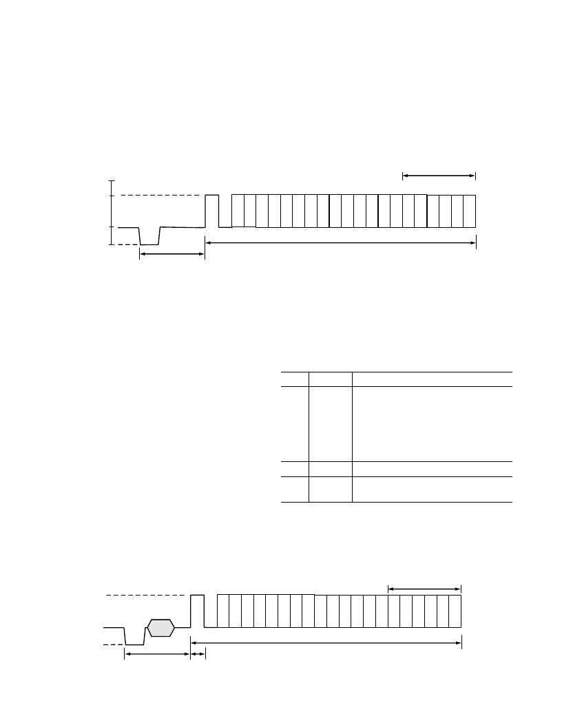
C0
C1
C2
C3
C4
C5
C6
C7
C8
C9 C10 C11 C12 C13 C14 C15 C16 C17 C18 C19
CRC SEQUENCE
21.2 s 0.22 s
22T
REF
5.8 s 0.15 s
6T
0mV
–300mV
70% 10%
BIT 1
T = 1/(f
33) = 963ns
f
= HORIZONTAL SCAN FREQUENCY
T 30ns
+700mV
BIT 20
Figure 80. CGMS Waveform
SD CGMS Data Registers 2–0
[Subaddresses 59h, 5Ah, and 5Bh]
The ADV7302A/ADV7303A supports Copy Generation Man-
agement System (CGMS) conforming to the standard. CGMS
data is transmitted on Line 20 of the odd fields and Line 283 of
even fields. Bits C/W05 and C/W06 control whether or not
CGMS data is output on odd and even fields. CGMS data can
only be transmitted when the ADV7302A/ADV7303A is config-
ured in NTSC mode. The CGMS data is 20 bits long, the
function of each of these bits is as shown below. The CGMS
data is preceded by a reference pulse of the same amplitude and
duration as a CGMS bit, see Figure 81.
If SD CGMS CRC [Address 59h, Bit 4] is set to a Logic “1,”
the last six bits, C19–C14, that comprise the 6-bit CRC check
sequence are calculated automatically on the ADV7302A/
ADV7303A based on the lower 14 bits (C0–C13) of the data in
the data registers and output with the remaining 14 bits to form
the complete 20 bits of the CGMS data. The calculation of the
CRC sequence is based on the polynomial:
x
x
6
1
+
+
with a preset value of 111111. If SD CGMS CRC [Address
59h, Bit 4] is set to a Logic “0,” then all 20 bits (C0–C19) are
output directly from the CGMS registers (no CRC calculated;
must be calculated by the user).
Table XXIV. Function of CGMS Bits
Word
Bit
Function
0
B1
Aspect Ratio
0 = 4:3
1 = 16:9
0 = Normal
1 = Letterbox
B2
Display Format
B3
B4–B6
Undefined
Identification Information about Video
and Other Signals (i.e., Audio)
1
B7–B10
Identification Signal. Incidental to Word 0.
2
B11–B14
Identification Signal and Information.
Incidental to Word 0.
C0
C1
C2
C3
C4
C5
C6
C7
C8
C9 C10 C11 C12 C13 C14 C15 C16 C17 C18 C19
CRC SEQUENCE
49.1 s 0.5 s
REF
11.2 s
0 IRE
–40 IRE
+70 IRE
+100 IRE
2.235 s 20ns
Figure 81. CGMS Waveform
相關(guān)PDF資料 |
PDF描述 |
|---|---|
| ADV7310 | Multiformat 216 MHz Video Encoder with Six NSV 12-Bit DACs |
| ADV7310KST | Multiformat 216 MHz Video Encoder with Six NSV 12-Bit DACs |
| ADV7311 | Multiformat 216 MHz Video Encoder with Six NSV 12-Bit DACs |
| ADV7311KST | Multiformat 216 MHz Video Encoder with Six NSV 12-Bit DACs |
| ADV7312 | Multiformat 11-Bit HDTV Video Encoder |
相關(guān)代理商/技術(shù)參數(shù) |
參數(shù)描述 |
|---|---|
| ADV73045701 | 制造商:LG Corporation 功能描述:Frame Assembly |
| ADV73045702 | 制造商:LG Corporation 功能描述:Frame Assembly |
| ADV73045703 | 制造商:LG Corporation 功能描述:Frame Assembly |
| ADV73045704 | 制造商:LG Corporation 功能描述:Frame Assembly |
| ADV73045753 | 制造商:LG Corporation 功能描述:Frame Assembly |
發(fā)布緊急采購(gòu),3分鐘左右您將得到回復(fù)。