- 您現(xiàn)在的位置:買賣IC網(wǎng) > PDF目錄374047 > ADV7303AKST (ANALOG DEVICES INC) Sand Paper; Abrasive Grade:T; Color:White; Pack Quantity:3; Roll Length:30ft; Width:4" PDF資料下載
參數(shù)資料
| 型號: | ADV7303AKST |
| 廠商: | ANALOG DEVICES INC |
| 元件分類: | 顏色信號轉(zhuǎn)換 |
| 英文描述: | Sand Paper; Abrasive Grade:T; Color:White; Pack Quantity:3; Roll Length:30ft; Width:4" |
| 中文描述: | COLOR SIGNAL ENCODER, PQFP64 |
| 封裝: | PLASTIC, MS-026BCD, LQFP-64 |
| 文件頁數(shù): | 47/68頁 |
| 文件大小: | 1177K |
| 代理商: | ADV7303AKST |
第1頁第2頁第3頁第4頁第5頁第6頁第7頁第8頁第9頁第10頁第11頁第12頁第13頁第14頁第15頁第16頁第17頁第18頁第19頁第20頁第21頁第22頁第23頁第24頁第25頁第26頁第27頁第28頁第29頁第30頁第31頁第32頁第33頁第34頁第35頁第36頁第37頁第38頁第39頁第40頁第41頁第42頁第43頁第44頁第45頁第46頁當(dāng)前第47頁第48頁第49頁第50頁第51頁第52頁第53頁第54頁第55頁第56頁第57頁第58頁第59頁第60頁第61頁第62頁第63頁第64頁第65頁第66頁第67頁第68頁
REV. A
ADV7302A/ADV7303A
–47–
Table XXI. Adaptive Filter Control on Step Input Signal
Address
Register Setting
00h
01h
02h
10h
11h
15h
20h
38h
39h
3Ah
3Bh
3Ch
3Dh
FCh
38h
20h
00h
81h
80h
00h
ACh
9Ah
88h
28h
3Fh
64h
All other register settings are 00h.
When changing the Adaptive Filter Mode to Mode B
[Address 15h, Bit 6], the output in Figure 67 can be obtained.
: 674mV
@: 446mV
: 332ns
@: 12.8ms
Figure 67. Output Signal from Adaptive Filter Control
The adaptive filter control can also be demonstrated using the
internally generated crosshatch test pattern and toggling the Adap-
tive Filter Control Bit [Address 15h, Bit 7], shown in Table XXII.
Table XXII. Adaptive Filter Control on Internal Test Pattern
Address
Register Setting
00h
01h
02h
10h
11h
15h
20h
38h
39h
3Ah
3Bh
3Ch
3Dh
FCh
38h
20h
00h
85h
80h
00h
ACh
9Ah
88h
28h
3Fh
64h
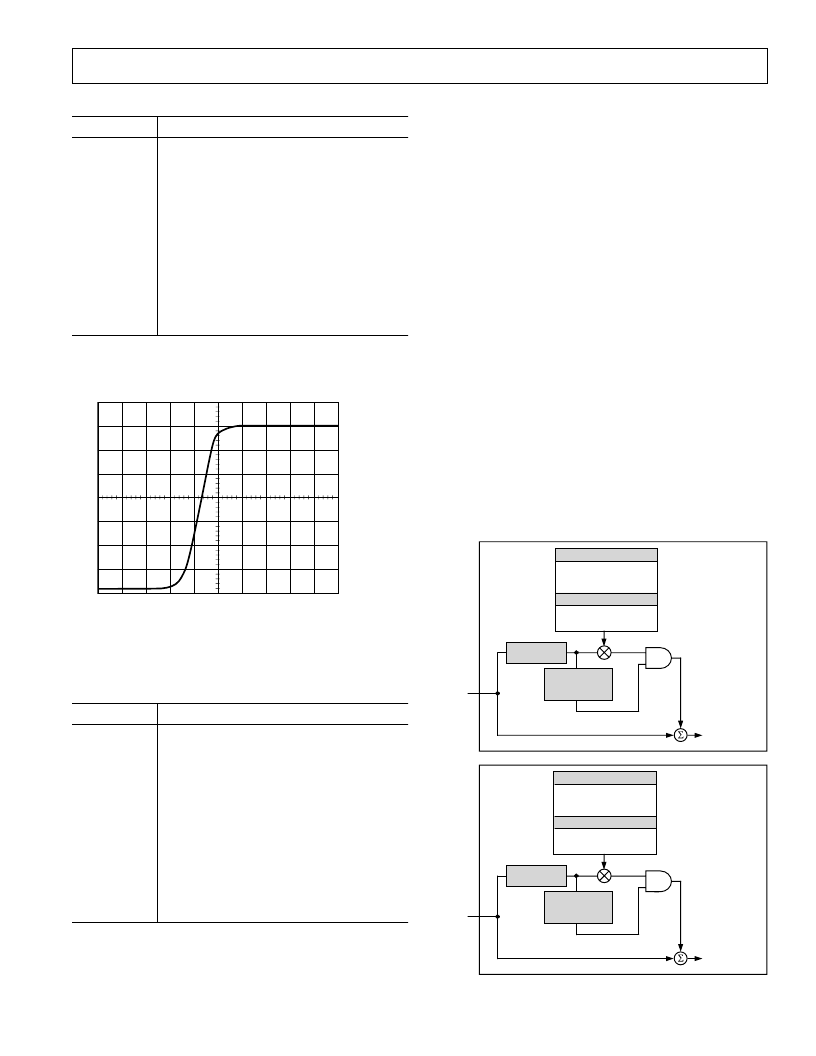
SD DIGITAL NOISE REDUCTION
[Subaddresses 63h, 64h, and 65h]
DNR is applied to the Y data only. A filter block selects the high
frequency, low amplitude components of the incoming signal
(DNR input select). The absolute value of the filter output is
compared to a programmable threshold value (DNR threshold
control). There are two DNR modes available: DNR Mode and
DNR Sharpness Mode.
In DNR Mode, if the absolute value of the filter output is smaller
than the threshold, it is assumed to be noise. A programmable
amount (coring gain border, coring gain data) of this noise signal
will be subtracted from the original signal.
In DNR Sharpness Mode, if the absolute value of the filter
output is less than the programmed threshold, it is assumed to
be noise, as before. Otherwise, if the level exceeds the threshold,
now being identified as a valid signal, a fraction of the signal
(coring gain border, coring gain data) will be added to the origi-
nal signal in order to boost high frequency components and to
sharpen the video image.
In MPEG systems it is common to process the video information
in blocks of 8
8 pixels for MPEG2 systems, or 16
MPEG1 systems (block size control). DNR can be applied to the
resulting block transition areas that are known to contain noise.
Generally, the block transition area contains two pixels. It is pos-
sible to define this area to contain four pixels (border area.)
It is also possible to compensate for variable block positioning
or differences in YCrCb pixel timing with the use of the DNR
block offset.
16 pixels for
BLOCK SIZE CONTROL
BORDER AREA
BLOCK OFFSET
CORING GAIN DATA
CORING GAIN BORDER
GAIN
DNR CONTROL
FILTER
OUTPUT
> THRESHOLD
INPUT FILTER
BLOCK
FILTER OUTPUT
< THRESHOLD
DNR OUT
MAIN SIGNAL PATH
ADD SIGNAL
ABOVE THRESHOLD
RANGE FROM
ORIGINAL SIGNAL
DNR
SHARPNESS
MODE
NOISE
SIGNAL PATH
Y DATA
INPUT
BLOCK SIZE CONTROL
BORDER AREA
BLOCK OFFSET
CORING GAIN DATA
CORING GAIN BORDER
GAIN
DNR CONTROL
FILTER
OUTPUT
< THRESHOLD
INPUT FILTER
BLOCK
FILTER OUTPUT
> THRESHOLD
DNR OUT
MAIN SIGNAL PATH
SUBTRACT SIGNAL
IN THRESHOLD
RANGE FROM
ORIGINAL SIGNAL
DNR MODE
NOISE
SIGNAL PATH
Y DATA
INPUT
Figure 68. DNR Block Diagram
相關(guān)PDF資料 |
PDF描述 |
|---|---|
| ADV7310 | Multiformat 216 MHz Video Encoder with Six NSV 12-Bit DACs |
| ADV7310KST | Multiformat 216 MHz Video Encoder with Six NSV 12-Bit DACs |
| ADV7311 | Multiformat 216 MHz Video Encoder with Six NSV 12-Bit DACs |
| ADV7311KST | Multiformat 216 MHz Video Encoder with Six NSV 12-Bit DACs |
| ADV7312 | Multiformat 11-Bit HDTV Video Encoder |
相關(guān)代理商/技術(shù)參數(shù) |
參數(shù)描述 |
|---|---|
| ADV73045701 | 制造商:LG Corporation 功能描述:Frame Assembly |
| ADV73045702 | 制造商:LG Corporation 功能描述:Frame Assembly |
| ADV73045703 | 制造商:LG Corporation 功能描述:Frame Assembly |
| ADV73045704 | 制造商:LG Corporation 功能描述:Frame Assembly |
| ADV73045753 | 制造商:LG Corporation 功能描述:Frame Assembly |
發(fā)布緊急采購,3分鐘左右您將得到回復(fù)。