- 您現(xiàn)在的位置:買賣IC網(wǎng) > PDF目錄374016 > ADM9240 (Analog Devices, Inc.) Low Cost Microprocessor System Hardware Monitor PDF資料下載
參數(shù)資料
| 型號: | ADM9240 |
| 廠商: | Analog Devices, Inc. |
| 英文描述: | Low Cost Microprocessor System Hardware Monitor |
| 中文描述: | 低成本的微處理器系統(tǒng)硬件監(jiān)視器 |
| 文件頁數(shù): | 19/22頁 |
| 文件大小: | 280K |
| 代理商: | ADM9240 |
ADM9240
–19–
REV. 0
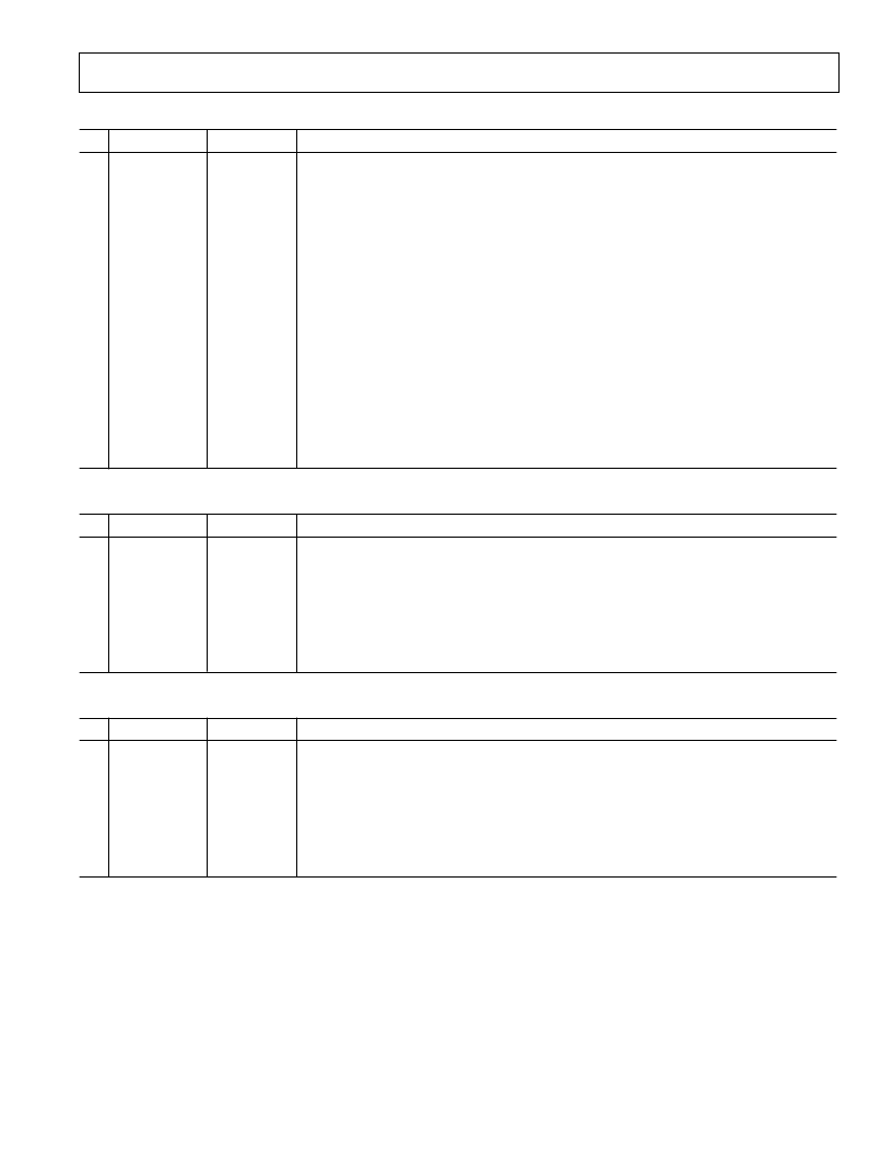
T able VII. Register 40h, Configuration Register (Power-On Default = 08h)
Bit
Name
R/
W
Description
0
ST ART
R/
W
Logic 1 enables startup of ADM9240, Logic 0 places it in standby mode. Caution: the out-
puts of the Interrupt pins will not be cleared if the user writes a zero to this location after an
interrupt has occurred (see “
INT
_Clear” bit). At startup, limit checking functions and scan-
ning begins. Note, all high and low limits should be set into the ADM9240 prior to turning
on this bit. (Power-Up Default = 0.)
Logic 1 enables the
INT
output. 1 = Enabled 0 = Disabled (Power-Up Default = 0).
Default = 0.
During Interrupt Service Routine (ISR) this bit is asserted Logic 1 to clear
INT
output
without affecting the contents of the Interrupt Status Register. T he device will stop monitor-
ing. It will resume upon clearing of this bit. (Power-Up Default = 1.)
Creates a
RESET
(Active Low) signal for 20 ms minimum (Power-Up Default = 0).
T his bit is cleared once the pulse goes active.
Default = 0.
A “1” outputs a minimum 20 ms active low pulse on the Chassis Intrusion pin. (Power-Up
Default = 0.) (Note: T his bit performs the same function as Bit 7 in Register 46h).
Logic 1 restores power-up default values to the Configuration register, Interrupt status regis-
ters, Interrupt Mask Registers, Fan Divisor Register and the T emperature Configuration
Register. T his bit automatically clears itself since the power-on default is zero.
1
2
3
INT
_Enable
Reserved
INT
_Clear
R/
W
R/
W
4
RESET
R/
W
5
6
Reserved
CI_Reset
R/
W
R/
W
7
Initialization
R/
W
T able VIII. Register 41h, Interrupt Status Register 1 (Power-On Default = 00h)
Bit
Name
R/
W
Description
0
1
2
3
4
5
6
7
+2.5 V_Error
V
CCP
_Error
+3.3 V_Error
+5 V_Error
T emp_Error
Reserved
FAN1_Error
FAN2_Error
Read Only
Read Only
Read Only
Read Only
Read Only
Read Only
Read Only
Read Only
A “1” indicates a high or low limit has been exceeded.
A “1” indicates a high or low limit has been exceeded.
A “1” indicates a high or low limit has been exceeded.
A “1” indicates a high or low limit has been exceeded.
A “1” indicates that a temperature interrupt has been set.
Undefined.
A “1” indicates that a fan count limit has been exceeded.
A “1” indicates that a fan count limit has been exceeded.
T able IX . Register 42h, Interupt Status Register 2 (Power-On Default = 00h)
Bit
Name
R/
W
Description
0
1
2
3
4
5
6
7
+12 V_Error
V
CCP2
_Error
Reserved
Reserved
Chassis_Error
Reserved
Reserved
Reserved
Read Only
Read Only
Read Only
Read Only
Read Only
Read Only
Read Only
Read Only
A “1” indicates a high or low limit has been exceeded.
A “1” indicates a high or low limit has been exceeded.
Undefined.
Undefined.
A “1” indicates chassis intrusion has gone high.
Undefined.
Undefined.
Undefined.
Note:
Any time the ST AT US Register is read out, the conditions (i.e., Register) that are read are automatically reset. In the case of the channel priority indication, if
two or more channels were out of limits, another indication would automatically be generated if it were not handled during the ISR. In the Mask Register, the errant
voltage interrupt may be disabled until the operator has time to clear the errant condition or set the limit higher/lower.
相關(guān)PDF資料 |
PDF描述 |
|---|---|
| ADM9240ARU | Low Cost Microprocessor System Hardware Monitor |
| ADM9261 | Triple- Power Supply Monitor(3路電源監(jiān)視器) |
| ADM9264ARN-REEL | Quad Power Supply Monitor for Desktop PCs |
| ADM9264ARN-REEL7 | Quad Power Supply Monitor for Desktop PCs |
| ADM9264 | Quad Power Supply Monitor for Desktop PCs |
相關(guān)代理商/技術(shù)參數(shù) |
參數(shù)描述 |
|---|---|
| ADM9240ARU | 制造商:Analog Devices 功能描述:Data Acquisition System, 6 Channel, 9 Bit, 24 Pin, Plastic, TSSOP |
| ADM9240ARU-REEL | 制造商:AD 制造商全稱:Analog Devices 功能描述:Low Cost Microprocessor System Hardware Monitor |
| ADM9240ARU-REEL7 | 制造商:Analog Devices 功能描述: |
| ADM9264 | 制造商:AD 制造商全稱:Analog Devices 功能描述:Quad Power Supply Monitor for Desktop PCs |
| ADM9264ARN | 制造商:Analog Devices 功能描述:Volt Supervisor Monitor 2.8V/3.3V/5V/12V 16-Pin SOIC N 制造商:Rochester Electronics LLC 功能描述:MULTI-SUPPLY HARDWARE MON - Bulk |
發(fā)布緊急采購,3分鐘左右您將得到回復(fù)。