- 您現(xiàn)在的位置:買賣IC網 > PDF目錄11767 > AD6620ASZ-REEL (Analog Devices Inc)IC DGTL RCVR DUAL 67MSPS 80-PQFP PDF資料下載
參數(shù)資料
| 型號: | AD6620ASZ-REEL |
| 廠商: | Analog Devices Inc |
| 文件頁數(shù): | 38/44頁 |
| 文件大小: | 0K |
| 描述: | IC DGTL RCVR DUAL 67MSPS 80-PQFP |
| 標準包裝: | 500 |
| 接口: | 并行/串行 |
| 電源電壓: | 3 V ~ 3.6 V |
| 封裝/外殼: | 80-BQFP |
| 供應商設備封裝: | 80-PQFP(14x14) |
| 包裝: | 帶卷 (TR) |
| 安裝類型: | 表面貼裝 |
第1頁第2頁第3頁第4頁第5頁第6頁第7頁第8頁第9頁第10頁第11頁第12頁第13頁第14頁第15頁第16頁第17頁第18頁第19頁第20頁第21頁第22頁第23頁第24頁第25頁第26頁第27頁第28頁第29頁第30頁第31頁第32頁第33頁第34頁第35頁第36頁第37頁當前第38頁第39頁第40頁第41頁第42頁第43頁第44頁
AD6620
–43–
REV. A
CLOCK
DVOUT1
DVOUT2
DVOUT3
DVOUT4
AD6620–1
AD6620–2
AD6620–3
AD6620–4
SELECTOR
OUTPUT
Q
I
Q
IQ
I
Q
I
Q
I
Q
I
Q
I
Q
I
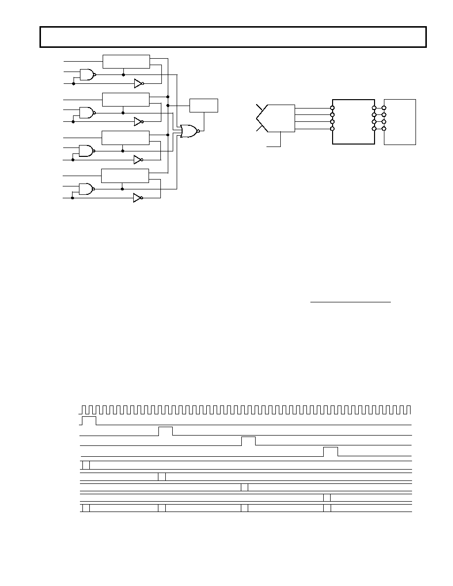
Figure 59. Timing for Parallel Processing
OE
INPUT LATCHING
DOUT1
CLOCK
DVOUT1
DOUT2
CLOCK
DVOUT2
DOUT3
CLOCK
DVOUT3
DOUT4
CLOCK
DVOUT4
OE
INPUT LATCHING
OE
INPUT LATCHING
OE
INPUT LATCHING
OUTPUT
LATCHING
Figure 58. Parallel Processing Output Selector
In the Output Selector above each of the DVOUT lines is ANDed
with main clock. This allows the data out of each of the AD6620s
to be properly latched into the input latches. The DVOUT line is
also responsible for placing the latched outputs on the internal
bus at the proper time. This data is then latched in the output
latch using the internal ORed clocking signals.
The timing for these events is shown in Figure 59. As shown,
the system clock is run at the specified rate. Then the RCF
timing control state machine is responsible for generating the
appropriate sync pulses. When each AD6620 completes its SOP
computation, it generates the DVOUT pulses shown below. Concur-
rently, each chip places its IQ data on the output pins of that
device. With this data, the output selector state machine com-
bines all of the data and places the data on the output bus.
Using the AD6620 in a Narrow Band System
A typical interconnection between the AD6600, AD6620 and a
General Purpose DSP is shown in Figure 65. This is an example
of an IF sampling narrow-band system and offers many techni-
cal and cost advantages over traditional solutions. In this example,
the AD6620 is in Diversity Channel Real Mode, with the AD6600
sampling a diversity antenna on its B channel. The AD6620
performs floating-point to fixed-point conversion, digital tuning,
digital filtering and decimation of the A/D output data.
MAIN
INPUT
DIVERSITY
INPUT
2 CLK
A/B OUT
3 RSSI BITS
11 DATA BITS
ENCODE
SCLK
SDI
SDO
SDFS
CLK
A/B
E[2...0]
IN[15...5]
AD6620
AD6600
SCLK
SDO
SDI
SDFS
DSP
Figure 60. Implementation of a Narrow Band Receiver
The 2
× CLK on the AD6600 is used as the processing CLK of
the AD6620. The use of this faster clock allows the RCF filter
to process up to twice as many taps per sample. The increased
number of taps available helps to improve the filter characteris-
tics. In some applications an even faster processing clock may be
necessary to allow for improved digital filter performance. In
this case the A/B pin of the AD6620 must be toggled when each
channel input is to be sampled.
For most narrow-band uses of the AD6600/AD6620 combina-
tion, a high oversampling ratio is desired. This spreads the
quantization noise of the A/D over a wider spectrum and allows
the digital filtering of the AD6620 to remove much of this noise.
This effectively increases the SNR of the AD6600. This process
of oversampling and digital filtering is called “process gain”
and its contribution to SNR can be calculated from the equa-
tion below.
PG
Sample Rate of Channel
Signal Bandwidth
=
10 log
__
_
The process of oversampling can also provide the benefit of
lowering the noise floor of the A/D. This can increase the effec-
tive dynamic range of a receiver if the sampling rate is chosen
such that the signal harmonics and/or intermodular distortion
(IMD) products fall out of the band of interest. In this case
these spurs could be filtered by the AD6620 and the quantiza-
tion noise would be the dominant dynamic range limitation of
the AD6600/AD6620 receiver solution.
相關PDF資料 |
PDF描述 |
|---|---|
| 6274291-2 | CONN JACK VERT PCB 75 OHM BNC |
| AD7669JNZ | IC I/O PORT 8BIT ANLG 28DIP |
| D38999/24FF11PA | CONN RCPT 11POS JAM NUT W/PINS |
| D38999/20JE26HN | CONN RCPT 26POS WALL MNT W/PINS |
| AD7569KNZ | IC I/O PORT 8BIT ANALOG 24DIP |
相關代理商/技術參數(shù) |
參數(shù)描述 |
|---|---|
| AD6620PCB | 制造商:AD 制造商全稱:Analog Devices 功能描述:65 MSPS Digital Receive Signal Processor |
| AD6620S | 制造商:AD 制造商全稱:Analog Devices 功能描述:65 MSPS Digital Receive Signal Processor |
| AD6620S/PCB | 制造商:Analog Devices 功能描述:DUAL CHANNEL DECIMATING RECEIV 制造商:Analog Devices 功能描述:SGNL PROCESSOR 169CSPBGA - Bulk |
| AD6622 | 制造商:AD 制造商全稱:Analog Devices 功能描述:Four-Channel, 75 MSPS Digital Transmit Signal Processor TSP |
| AD6622AS | 制造商:Analog Devices 功能描述:Transmit Signal Processor 128-Pin MQFP 制造商:Rochester Electronics LLC 功能描述:4 CHANNEL 65 MSPS DIGITAL UPCONVERTER - Bulk |
發(fā)布緊急采購,3分鐘左右您將得到回復。