- 您現(xiàn)在的位置:買賣IC網(wǎng) > PDF目錄368957 > 28F160F3 5V/3.3V or Adjustable, Low-Dropout, Low-IQ, 500mA Linear Regulators PDF資料下載
參數(shù)資料
| 型號: | 28F160F3 |
| 英文描述: | 5V/3.3V or Adjustable, Low-Dropout, Low-IQ, 500mA Linear Regulators |
| 中文描述: | 快速啟動塊閃存的8和16兆比特 |
| 文件頁數(shù): | 19/47頁 |
| 文件大小: | 277K |
| 代理商: | 28F160F3 |
第1頁第2頁第3頁第4頁第5頁第6頁第7頁第8頁第9頁第10頁第11頁第12頁第13頁第14頁第15頁第16頁第17頁第18頁當(dāng)前第19頁第20頁第21頁第22頁第23頁第24頁第25頁第26頁第27頁第28頁第29頁第30頁第31頁第32頁第33頁第34頁第35頁第36頁第37頁第38頁第39頁第40頁第41頁第42頁第43頁第44頁第45頁第46頁第47頁

E
FAST BOOT BLOCK DATASHEET
19
PRODUCT PREVIEW
ADV# (V)
A
19-0
(A)
Valid
Address
CLK (C)
DQ
15-0
(D/Q)
Valid
Output
DQ
15-0
(D/Q)
Valid
Output
Valid
Output
Valid
Output
Valid
Output
DQ
15-0
(D/Q)
Valid
Output
Valid
Output
Valid
Output
Valid
Output
DQ
15-0
(D/Q)
Valid
Output
Valid
Output
DQ
15-0
(D/Q)
Valid
Output
Valid
Output
Valid
Output
Valid
Output
Code 2
Code 3
Code 4
Code 5
Code 6
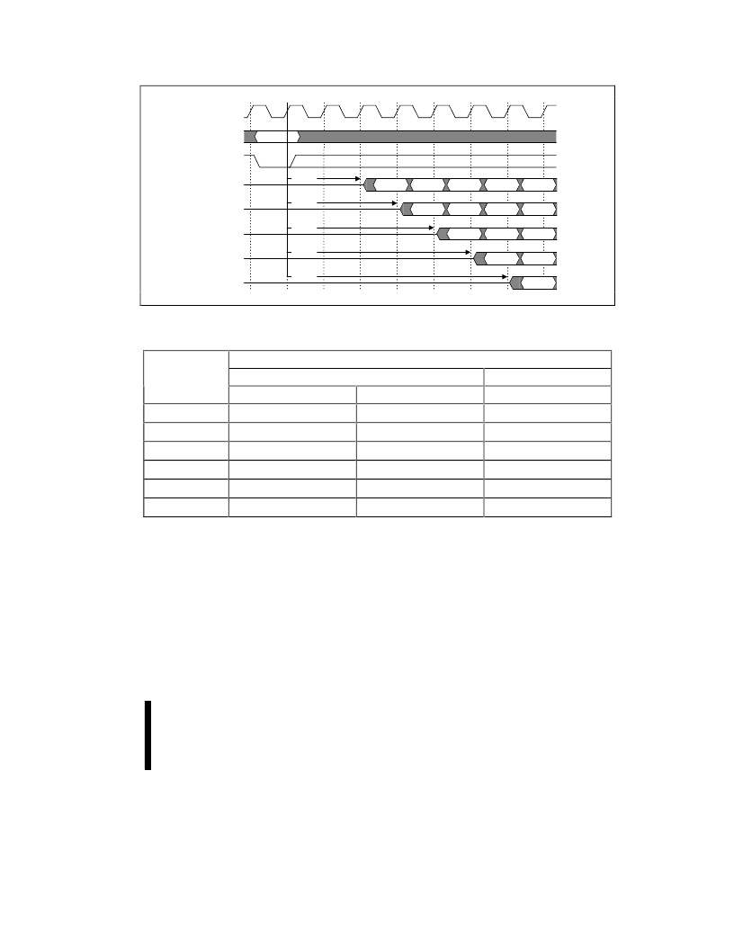
Figure 5. Frequency Configuration
Table 7. Frequency Configuration Settings
(1)
Frequency
Input CLK Frequency
Configuration
Product = -90
Product = -120
Code
V
CC
= 3.0 V-3.6 V
V
CC
= 2.7 V-3.6 V
V
CC
= 2.7 V-3.6 V
1
Reserved
Reserved
Reserved
2
≤
27 MHz
≤
25 MHz
≤
20 MHz
3
≤
40 MHz
≤
33 MHz
≤
28 MHz
4
≤
54 MHz
≤
50 MHz
≤
40 MHz
5
≤
66 MHz
≤
60 MHz
≤
50 MHz
6
-
≤
66 MHz
≤
60 MHz
NOTES:
1.
Reference Section 4.1. Automotive Temperature Frequency Configuration Settings for the corresponding frequency
configuration codes to different input CLK frequencies.
4.9
Set Read Configuration
Command
The Set Read Configuration command writes data
to the read configuration register. This operation is
initiated by a two-cycle command sequence. Read
configuration setup is written, followed by a second
write that specifies the data to be written to the read
configuration register. This data is placed on the
address bus, A
15:0
, and is latched on the rising
edge of ADV#, CE#, or WE# (whichever occurs
first). The read configuration data sets the device’s
read
configuration,
burst
configuration, and burst length. The command
functions independently of the applied V
voltage.
After executing this command, the device returns to
read array mode.
order,
frequency
4.9.1
READ CONFIGURATION
The device supports two high performance read
configurations:
asynchronous
page-mode
and
相關(guān)PDF資料 |
PDF描述 |
|---|---|
| 28F800F3 | 3 Volt Fast Boot Block Flash Memory(3 V 8M位快速引導(dǎo)塊閃速存儲器) |
| 28F160F3 | 16MBIT Fast Boot Block Flash Memory(16兆位的快速引導(dǎo)塊閃速存儲器) |
| 28F2001BX-T | 5V/3.3V or Adjustable, Low-Dropout, Low-IQ, 500mA Linear Regulators |
| 28F256 | FASTENERS, TIES CABLE |
| 28F256 | 256 Kilobit (32 K x 8-Bit) CMOS 12.0 Volt, Bulk Erase Flash Memory |
相關(guān)代理商/技術(shù)參數(shù) |
參數(shù)描述 |
|---|---|
| 28F160F3B95 | 制造商:Intel 功能描述: |
| 28F160S3 | 制造商:INTEL 制造商全稱:Intel Corporation 功能描述:WORD-WIDE FlashFile MEMORY FAMILY |
| 28F160S3HTL10A | 制造商: 功能描述: 制造商:undefined 功能描述: |
| 28F160S3HT-L10A | 制造商: 功能描述: 制造商:undefined 功能描述: |
| 28F160S3HT-L75A | 制造商: 功能描述: 制造商:undefined 功能描述: |
發(fā)布緊急采購,3分鐘左右您將得到回復(fù)。