- 您現(xiàn)在的位置:買賣IC網(wǎng) > PDF目錄383960 > TMX32C6411GLZ (Texas Instruments, Inc.) Anti-Static Storage Bags; External Height:5"; External Width:3"; Thickness:0.12" PDF資料下載
參數(shù)資料
| 型號: | TMX32C6411GLZ |
| 廠商: | Texas Instruments, Inc. |
| 英文描述: | Anti-Static Storage Bags; External Height:5"; External Width:3"; Thickness:0.12" |
| 中文描述: | 定點數(shù)字信號處理器 |
| 文件頁數(shù): | 70/119頁 |
| 文件大小: | 1742K |
| 代理商: | TMX32C6411GLZ |
第1頁第2頁第3頁第4頁第5頁第6頁第7頁第8頁第9頁第10頁第11頁第12頁第13頁第14頁第15頁第16頁第17頁第18頁第19頁第20頁第21頁第22頁第23頁第24頁第25頁第26頁第27頁第28頁第29頁第30頁第31頁第32頁第33頁第34頁第35頁第36頁第37頁第38頁第39頁第40頁第41頁第42頁第43頁第44頁第45頁第46頁第47頁第48頁第49頁第50頁第51頁第52頁第53頁第54頁第55頁第56頁第57頁第58頁第59頁第60頁第61頁第62頁第63頁第64頁第65頁第66頁第67頁第68頁第69頁當前第70頁第71頁第72頁第73頁第74頁第75頁第76頁第77頁第78頁第79頁第80頁第81頁第82頁第83頁第84頁第85頁第86頁第87頁第88頁第89頁第90頁第91頁第92頁第93頁第94頁第95頁第96頁第97頁第98頁第99頁第100頁第101頁第102頁第103頁第104頁第105頁第106頁第107頁第108頁第109頁第110頁第111頁第112頁第113頁第114頁第115頁第116頁第117頁第118頁第119頁
SPRS196H MARCH 2002 REVISED JULY 2004
70
POST OFFICE BOX 1443
HOUSTON, TEXAS 772511443
PARAMETER MEASUREMENT INFORMATION (CONTINUED)
timing parameters and board routing analysis
The timing parameter values specified in this data sheet do
not
include delays by board routings. As a good
board design practice, such delays must
always
be taken into account. Timing values may be adjusted by
increasing/decreasing such delays. TI recommends utilizing the available I/O buffer information specification
(IBIS) models to analyze the timing characteristics correctly. To properly use IBIS models to attain accurate
timing analysis for a given system, see the
Using IBIS Models for Timing Analysis
application report (literature
number SPRA839). If needed, external logic hardware such as buffers may be used to compensate any timing
differences.
For inputs, timing is most impacted by the round-trip propagation delay from the DSP to the external device and
from the external device to the DSP. This round-trip delay tends to negatively impact the input setup time margin,
but also tends to improve the input hold time margins (see Table 26 and Figure 15).
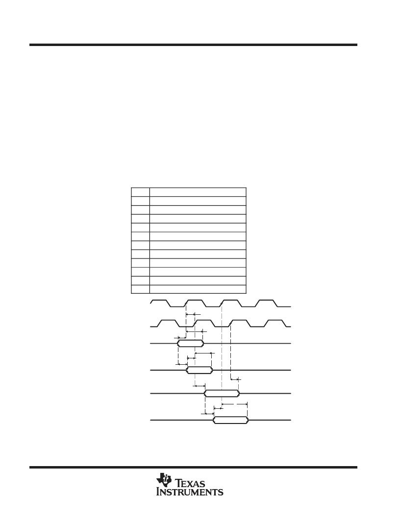
Figure 15 represents a general transfer between the DSP and an external device. The figure also represents
board route delays and how they are perceived by the DSP and the external device.
Table 26. Board-Level Timings
Example (see Figure 15)
NO.
DESCRIPTION
1
Clock route delay
2
Minimum DSP hold time
3
Minimum DSP setup time
4
External device hold time requirement
5
External device setup time requirement
6
Control signal route delay
7
External device hold time
8
External device access time
9
DSP hold time requirement
10
DSP setup time requirement
11
Data route delay
1
2
3
4
5
6
7
8
10
11
ECLKOUT
(Output from DSP)
ECLKOUT
(Input to External Device)
Control Signals
(Output from DSP)
Control Signals
(Input to External Device)
Data Signals
(Output from External Device)
Data Signals
(Input to DSP)
9
Control signals include data for Writes.
Data signals are generated during Reads from an external device.
Figure 15. Board-Level Input/Output Timings
相關PDF資料 |
PDF描述 |
|---|---|
| TMP320C6411GLZ | FIXED POINT DIGITAL SIGNAL PROCESSOR |
| TMP470R1B768PGE | 16/32-Bit RISC Flash Microcontroller |
| TMP47C020 | Transient Voltage Suppressor Diodes |
| TMP47C020G | Transient Voltage Suppressor Diodes |
| TMP47C050 | Transient Voltage Suppressor Diodes |
相關代理商/技術參數(shù) |
參數(shù)描述 |
|---|---|
| TMX32C6414EGLZ6E3 | 制造商:Rochester Electronics LLC 功能描述:- Bulk |
| TMX32C6415EGLZ5E0 | 制造商:Rochester Electronics LLC 功能描述:LAPLACE, REV. 2.0, 500 MHZ, 100 MHZ EMIF - Bulk |
| TMX32C6416EGLZ5E0 | 制造商:Rochester Electronics LLC 功能描述:- Bulk |
| TMX32TCI6482BZTZA2 | 制造商:Texas Instruments 功能描述: |
| TMX32TCI6616BXCYPA | 制造商:Texas Instruments 功能描述: |
發(fā)布緊急采購,3分鐘左右您將得到回復。