- 您現(xiàn)在的位置:買賣IC網(wǎng) > PDF目錄384004 > TLC320AD81C (Texas Instruments, Inc.) Stereo Audio Digital Equalizer DC PDF資料下載
參數(shù)資料
| 型號: | TLC320AD81C |
| 廠商: | Texas Instruments, Inc. |
| 英文描述: | Stereo Audio Digital Equalizer DC |
| 中文描述: | 立體聲音頻數(shù)字均衡器直流 |
| 文件頁數(shù): | 17/47頁 |
| 文件大小: | 185K |
| 代理商: | TLC320AD81C |
第1頁第2頁第3頁第4頁第5頁第6頁第7頁第8頁第9頁第10頁第11頁第12頁第13頁第14頁第15頁第16頁當(dāng)前第17頁第18頁第19頁第20頁第21頁第22頁第23頁第24頁第25頁第26頁第27頁第28頁第29頁第30頁第31頁第32頁第33頁第34頁第35頁第36頁第37頁第38頁第39頁第40頁第41頁第42頁第43頁第44頁第45頁第46頁第47頁
2–5
2.8
Control parameters for the TLC320AD81C are loaded with an I
2
C master interface. Information is loaded
into the registers defined in appendix A, Software Interface The I
2
C bus uses two pins, SDA (data) and SCL
(clock), to communicate between integrated circuits in a system. This device may be addressed by sending
a unique 7-bit slave address plus R/W bit (1 byte). All compatible devices share the same pins via a
bidirectional bus using a wire-ANDed connection. A pullup resistor must be used to set the high level on the
bus. The TLC320AD81C operates in standard mode up to 100 kbps with as many devices on the bus as
desired up to the capacitance load limit of 400 pF. Additionally, the TLC320AD81C operates only in slave
mode; therefore, at least one device connected to the I
2
C bus with this device must operate in master mode.
I
2
C Protocol
The bus standard uses transitions on the data pin (SDA) while the clock is high to indicate a start and stop
condition. A high-to-low transition on SDA indicates a start, and a low-to-high transition indicates a stop.
Normal data bit transitions must occur within the low time of the clock period. These conditions are shown
in Figure 2–4. These start and stop conditions for the I
2
C bus are required by standard protocol to be
generated by the master. The master must also generate the 7-bit slave address and the read/write (R/W)
bit to open communication with another device and then wait for an acknowledge condition. The slave holds
the SDA bit low during the acknowledge clock period to indicate an acknowledgment. When this occurs, the
master begins transmitting. After each 8-bit word, an acknowledgment must be transmitted by the receiving
device. There is no limit on the number of bytes that may be transmitted between a start and stop condition.
When the last word has been transferred, the master must generate a stop condition to release the bus. A
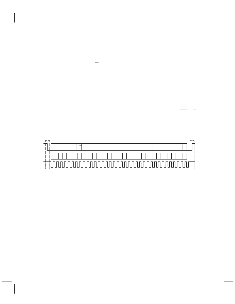
generic data transfer sequence is shown in Figure 2–4.
Serial Control Interface
2.8.1
7 Bit Slave Address
R/W
8 Bit Register Address (N)
A
A
8 Bit Register Data For
Address (N)
A
8 Bit Register Data For
Address (N)
A
7
6
5
4
3
2
1
0
7
6
5
4
3
2
1
0
7
6
5
4
3
2
1
0
7
6
5
4
3
2
1
0
Start
Stop
SDA
SCL
Figure 2–4. Typical I
2
C Data Transfer Sequence
The definitions used by the I
2
C protocol are listed below.
Transmitter
Receiver
Master
The device that sends data
The device that receives data
The device that initiates a transfer, generates clock signals, and terminates the
transfer
The device addressed by the master
More than one master can attempt to control the bus at the same time without
corrupting the message.
Procedure to ensure the message is not corrupted when two masters attempt to
control the bus
Procedure to synchronize the clock signals of two or more devices
Slave
Multi-master
Arbitration
Synchronization
相關(guān)PDF資料 |
PDF描述 |
|---|---|
| TLC339CDB | LinCMOSE MICROPOWER QUAD COMPARATORS |
| TLC339CDBR | LinCMOSE MICROPOWER QUAD COMPARATORS |
| TLC34058-110M | 256 ?24 COLOR PALETTE |
| TLC354MD | LinCMOSE QUADRUPLE DIFFERENTIAL COMPARATORS |
| TLC354MN | LinCMOSE QUADRUPLE DIFFERENTIAL COMPARATORS |
相關(guān)代理商/技術(shù)參數(shù) |
參數(shù)描述 |
|---|---|
| TLC320AD81CDBT | 制造商:Rochester Electronics LLC 功能描述:- Tape and Reel |
| TLC320AD90 | 制造商:TI 制造商全稱:Texas Instruments 功能描述:Stereo Audio Codec |
| TLC320AD91 | 制造商:TI 制造商全稱:Texas Instruments 功能描述:Stereo Audio Codec |
| TLC320AD91CPT | 制造商:Rochester Electronics LLC 功能描述:- Bulk |
| TLC320V320CFN | 制造商:Texas Instruments 功能描述: |
發(fā)布緊急采購,3分鐘左右您將得到回復(fù)。