- 您現(xiàn)在的位置:買賣IC網(wǎng) > PDF目錄383953 > TLC2942PW (Texas Instruments, Inc.) HIGH-PERFORMANCE DUAL PHASE-LOCKED LOOP BUILDING BLOCK PDF資料下載
參數(shù)資料
| 型號: | TLC2942PW |
| 廠商: | Texas Instruments, Inc. |
| 英文描述: | HIGH-PERFORMANCE DUAL PHASE-LOCKED LOOP BUILDING BLOCK |
| 中文描述: | 高效能雙鎖相環(huán)積木 |
| 文件頁數(shù): | 19/28頁 |
| 文件大小: | 459K |
| 代理商: | TLC2942PW |
第1頁第2頁第3頁第4頁第5頁第6頁第7頁第8頁第9頁第10頁第11頁第12頁第13頁第14頁第15頁第16頁第17頁第18頁當前第19頁第20頁第21頁第22頁第23頁第24頁第25頁第26頁第27頁第28頁
TLC2942
HIGH-PERFORMANCE DUAL PHASE-LOCKED LOOP BUILDING BLOCK
SLAS146B – NOVEMBER 1996 – REVISED JUNE 1997
19
POST OFFICE BOX 655303
DALLAS, TEXAS 75265
APPLICATION INFORMATION
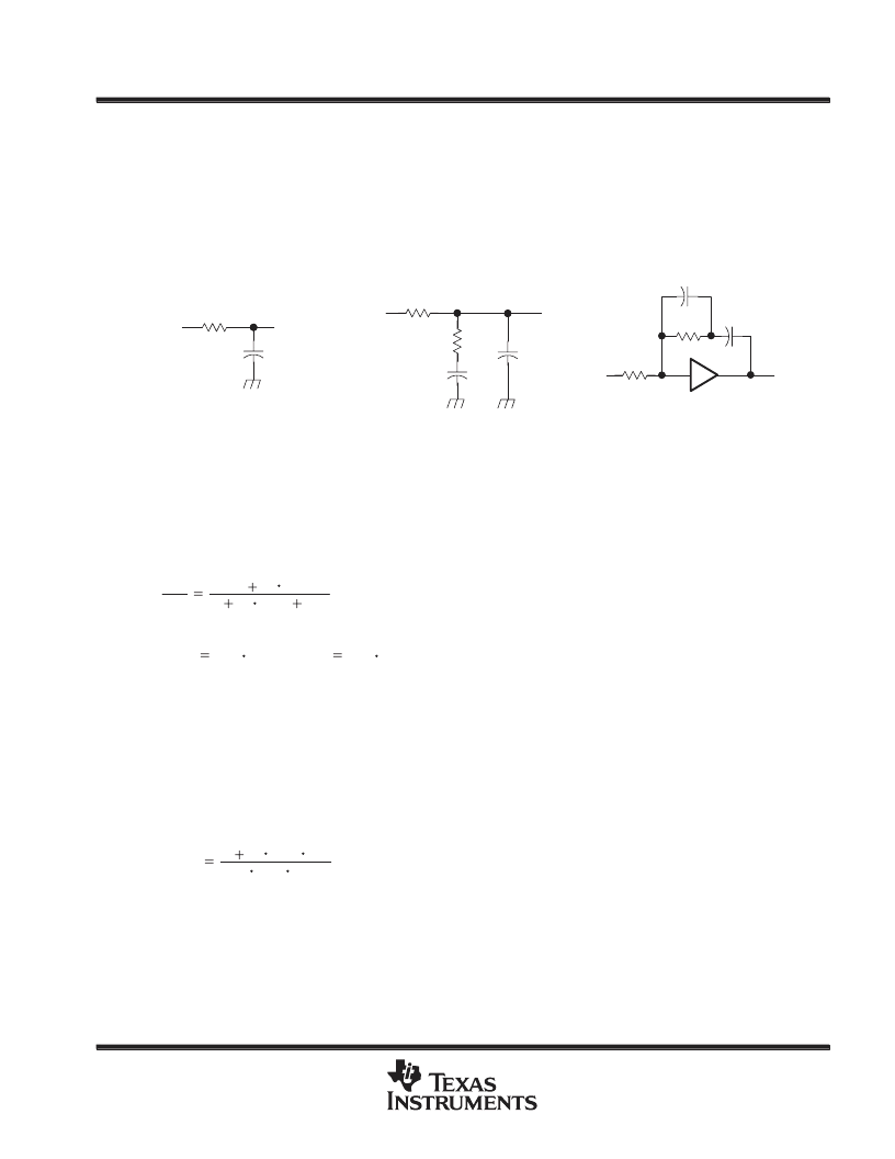
low-pass-filter (LPF) configurations
Many excellent references are available that include detailed design information about LPFs and they should
be consulted for additional information. Lag-lead filters or active filters are often used. Examples of LPFs are
shown in Figure 25. When the active filter of Figure 25(c) is used, the reference should be applied to F
IN
-B
because of the amplifier inversion. Also, in practical filter implementations, C2 is used as additional filtering at
the VCO input. The value of C2 should be equal to or less than one-tenth the value of C1.
R1
C1
T1 = C1R1
(a) LAG FILTER
R1
C1
T1 = C1R1
T2 = C1R2
R2
(b) LAG-LEAD FILTER
R2
C1
R1
T1 = C1R1
T2 = C1R2
(c) ACTIVE FILTER
A
–
VI
VO
VI
VO
VI
C2
VO
C2
Figure 25. LPF Examples for PLL
the passive filter
The transfer function for the low-pass filter shown in Figure 25(b) is:
VO
VIN
1
s
(T1
T2
1
s
T2)
Where
T1
R1
C1 and T2
R2
C1
(2)
Using this filter makes the closed loop PLL system a type 1 second-order system. The response curves of this
system to a unit step are shown in Figure 26.
the active filter
When using the active filter shown in Figure 25(c), the phase detector inputs must be reversed since the filter
adds an additional inversion. Therefore, the input reference frequency should be applied to the F
IN
-B terminal
and the output of the VCO divider should be applied to the input reference terminal, F
IN
-A.
The transfer function for the active filter shown in Figure 25(c) is:
F(s)
1
s
R2
C1
s
R1
C1
(3)
Using this filter makes the closed loop PLL system a type 2 second-order system. The response curves of this
system to a unit step are shown in Figure 27.
相關PDF資料 |
PDF描述 |
|---|---|
| TLC32040C | ANALOG INTERFACE CIRCUITS |
| TLC32040I | ANALOG INTERFACE CIRCUITS |
| TLC32041C | ANALOG INTERFACE CIRCUITS |
| TLC32041CFN | ANALOG INTERFACE CIRCUITS |
| TLC32041I | ANALOG INTERFACE CIRCUITS |
相關代理商/技術參數(shù) |
參數(shù)描述 |
|---|---|
| TLC2943IDB | 制造商:Rochester Electronics LLC 功能描述:- Bulk |
| TLC-2C-0164 | 制造商:KATO/COILTHREAD 功能描述: |
| TLC-2C-0164W | 制造商:KATO/COILTHREAD 功能描述: |
| TLC-2C-0164Y | 制造商:KATO/COILTHREAD 功能描述: |
| TLC-2C-0246 | 制造商:KATO/COILTHREAD 功能描述: |
發(fā)布緊急采購,3分鐘左右您將得到回復。