- 您現(xiàn)在的位置:買賣IC網(wǎng) > PDF目錄98151 > T90FJR-5VV (ATMEL CORP) SPECIALTY CONSUMER CIRCUIT, PQFP128 PDF資料下載
參數(shù)資料
| 型號: | T90FJR-5VV |
| 廠商: | ATMEL CORP |
| 元件分類: | 消費家電 |
| 英文描述: | SPECIALTY CONSUMER CIRCUIT, PQFP128 |
| 封裝: | PLASTIC, VQFP-128 |
| 文件頁數(shù): | 4/42頁 |
| 文件大小: | 358K |
| 代理商: | T90FJR-5VV |
第1頁第2頁第3頁當前第4頁第5頁第6頁第7頁第8頁第9頁第10頁第11頁第12頁第13頁第14頁第15頁第16頁第17頁第18頁第19頁第20頁第21頁第22頁第23頁第24頁第25頁第26頁第27頁第28頁第29頁第30頁第31頁第32頁第33頁第34頁第35頁第36頁第37頁第38頁第39頁第40頁第41頁第42頁
12
4152B–ASSP–09/05
A/T90FJR
Note:
(1): The WAIT / ACK output is either WAIT or ACK formatted according to the WAIT / ACK pin set-
tings (active level, driving structure).
(2): Depending on the write access type, CE can be either CE1A# or CE1B# for access to memory
or IO to module A or B, CE2A# or CE2B# for access in EC (Extended Channel) mode or even
EXTCS for access to external device in regenerate mode
(3): REG# signal is not asserted during a common memory or external access.
(4): WE# signal is asserted during a memory access (attribute or common). It is replaced by
IOWR# during an IO write cycle, an EC (Extended Channel) write cycle (using CE2A# or CE2B#)
or an external access in regenerate mode.
(5): t4 can be lengthened by the insertion of wait cycles. When the destination module asserts
WAIT# signal, the t4 cycles counter stops until WAIT# becomes inactive anew.
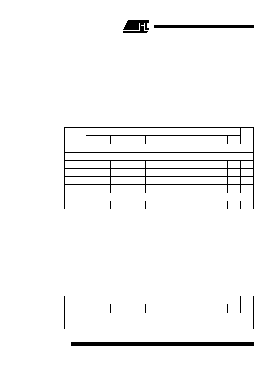
Memory write is valid for both attribute and common memory access. Timings are given in
CIMaX clock cycles. They are calculated to comply with PCMCIA specifications when 27MHz
clock is used.
Note:
1. these timings are given for a load of 50 pF on WAIT/ACK pin.
2. 1.5 cycle corresponds to the start cycle detection time. t1 depends actually on the previous
cycle completion which depends on t8 and t10 read timings. So t1 ranges from 3.5 to 6.5
cycles.
Note:
t0: delay between start of a write cycle and activation of WAIT
t1: delay between start of a write cycle and assertion of CE and REG# (if necessary for the current
cycle)
t2: delay to assertion of the write signal (WE# or IOWR#) after the start of the write cycle
t3: delay to assertion of the write signal (WE# or IOWR#) after the assertion of CE
t4: write cycle duration. This delay can be lengthened by the assertion of the module WAIT# pin
t5: delay between deassertion of the write signal and deassertion of CE, REG# and WAIT and
assertion of ACK indicating to the processor the end of its write cycle
t6: delay between end of the write cycle and deassertion of ACK
t7: delay between enabling of the data bus and write signal assertion. This delay is necessary
when a write cycle is immediately following a read cycle (see t10 in read cycle)
The corresponding timings are given below for a 27 MHz clock:
Memory write
IO,
EC,
Ext
600ns
250ns
200ns
150ns
100ns
t0 max
(1)
26 ns
t1 max
1.5 cycle + 26 ns
(2)
t2 min
2
1
2
t3
2
1
2
t4
9
5
4
3
2
5
t5
2
1
t6 max
(1)
26 ns
t7 min
1
2
Memory write
IO,
EC,
Ext
600ns
250ns
200ns
150ns
100ns
t0 max
24 ns
t1 max
80 ns
(from start cycle detection – see note in table above)
相關PDF資料 |
PDF描述 |
|---|---|
| TA1201AN | SPECIALTY CONSUMER CIRCUIT, PDIP56 |
| TA1201BN | SPECIALTY CONSUMER CIRCUIT, PDIP56 |
| TA1201CNG | SPECIALTY CONSUMER CIRCUIT, PDIP56 |
| TA1204AF | SPECIALTY CONSUMER CIRCUIT, PQFP44 |
| TA1209F | AM/FM, AUDIO/VIDEO DEMODULATOR, PQFP48 |
相關代理商/技術參數(shù) |
參數(shù)描述 |
|---|---|
| T90H1D12-12 | 制造商:TE Connectivity 功能描述: |
| T90H1D12-24 | 制造商:TE Connectivity 功能描述: |
| T90H1D12-24-08 | 功能描述:通用繼電器 POWER RELAY RoHS:否 制造商:Omron Electronics 觸點形式:1 Form A (SPST-NO) 觸點電流額定值:150 A 線圈電壓:24 VDC 線圈電阻:144 Ohms 線圈電流:167 mA 切換電壓:400 V 安裝風格:Chassis 觸點材料: |
| T90H1D12-24-18 | 功能描述:通用繼電器 1FormA SPST 18V 30A RoHS:否 制造商:Omron Electronics 觸點形式:1 Form A (SPST-NO) 觸點電流額定值:150 A 線圈電壓:24 VDC 線圈電阻:144 Ohms 線圈電流:167 mA 切換電壓:400 V 安裝風格:Chassis 觸點材料: |
| T90H1D12-24-20 | 功能描述:通用繼電器 T90H1D12-24-20=T90 RoHS:否 制造商:Omron Electronics 觸點形式:1 Form A (SPST-NO) 觸點電流額定值:150 A 線圈電壓:24 VDC 線圈電阻:144 Ohms 線圈電流:167 mA 切換電壓:400 V 安裝風格:Chassis 觸點材料: |
發(fā)布緊急采購,3分鐘左右您將得到回復。