- 您現(xiàn)在的位置:買賣IC網(wǎng) > PDF目錄382355 > MX803A (Electronic Theatre Controls, Inc.) Audio Signaling Processor PDF資料下載
參數(shù)資料
| 型號(hào): | MX803A |
| 廠商: | Electronic Theatre Controls, Inc. |
| 英文描述: | Audio Signaling Processor |
| 中文描述: | 音頻信號(hào)處理器 |
| 文件頁(yè)數(shù): | 6/26頁(yè) |
| 文件大小: | 225K |
| 代理商: | MX803A |
第1頁(yè)第2頁(yè)第3頁(yè)第4頁(yè)第5頁(yè)當(dāng)前第6頁(yè)第7頁(yè)第8頁(yè)第9頁(yè)第10頁(yè)第11頁(yè)第12頁(yè)第13頁(yè)第14頁(yè)第15頁(yè)第16頁(yè)第17頁(yè)第18頁(yè)第19頁(yè)第20頁(yè)第21頁(yè)第22頁(yè)第23頁(yè)第24頁(yè)第25頁(yè)第26頁(yè)

Audio Signaling Processor
6
MX803A PRELIMINARY INFORMATION
1996 MX
COM, INC.
Tele: 800 638 5577 910 744 5050 Fax: 910 744 5054
Doc. # 20480122.003
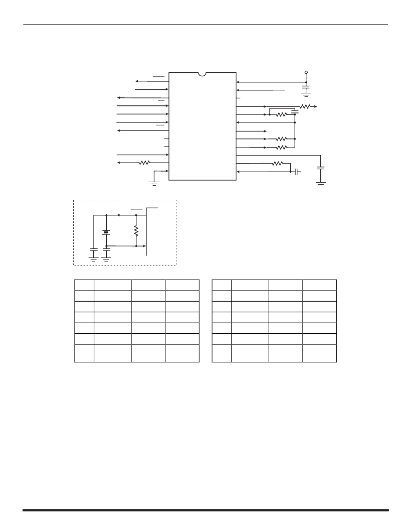
3. External Components
MX803A
INSET
SBELOW
1
2
3
4
5
6
7
8
9
10
11
12
24
23
22
21
20
19
18
17
16
15
14
13
XTAL
XTAL/CLOCK
REPLY DATA
CS
COMMAND DATA
LOGIC INPUT
IRQ
AUDIO SWITCH IN
AUDIO SWITCH OUT
V
R
R
X
C
C
C
C
R
R
R
R
C
C
V
BIAS
V
BIAS
SS
7
1
1
4
1
2
3
2
4
R
6
3
5
5
6
V
DD
SERIAL CLOCK
SWITCHED SUM OUT
SUM OUT
SUM IN
CAL/CUES OUT
TONE 2 OUT
TONE 1 OUT
SIGNAL BIAS
RX AUDIO IN
XTAL
XTAL/CLOCK
1
2
MX803A
TONE LEVEL
AND GAIN
COMPONENTS
R1
R2
R3
R4
R5
R6
R7
1.0M
2.0M
100k
82.0k
122k
100k
100k
±10%
±10%
±10%
±10%
±10%
±10%
±10%
C1
C2
C3
C4
C5
C6
X1
0.1
μ
F
1.0
μ
F
33.0pF
33.0pF
22.0pF
1.0
μ
F
4.00MH
z
±20%
±20%
±20%
±20%
±20%
±20%
Note 2, 3
Note 2, 3
Note 2, 3
Note 2
Note 2, 5
Note 4
Note 4
Note 3
Note 1, 4
Figure 2: Recommended External Components
Notes:
1. Xtal/clock components described are recommended in accordance with MX-COM's Application Note on Standard and
DBS 800 Crystal Oscillator Circuits (April 1990). For best results, a crystal oscillator design should drive the clock
inverter input with signal levels of at least 40% of V
DD
, peak to peak. Tuning fork crystals generally cannot meet this
requirement. To obtain crystal oscillator design assistance, consult your crystal manufacturer.
2. System Components whose values are calculated to allow the MX803A to operate with other DBS 800 microcircuits.
Figure 3 shows these components used in the system signal paths.
3. R3, R4, R5 and C5 are tone mixing components calculated to provide a 3dB tone differential (twist) for use in a DTMF
configuration. Single tone output levels are set independently.
4. When X1 > 5.00MHz, C3 = C4 = 18pF
5. R7 provides modulation level and matching outputs for the MX803A.
相關(guān)PDF資料 |
PDF描述 |
|---|---|
| MX812 | VSR CODEC WITH DRAM CONTROL |
| MX812DW | VSR CODEC WITH DRAM CONTROL |
| MX812J | VSR CODEC WITH DRAM CONTROL |
| MX841 | White LED Step-Up Converter |
| MX88L284AEC | Highly integration chip for Flat Panel Display application |
相關(guān)代理商/技術(shù)參數(shù) |
參數(shù)描述 |
|---|---|
| MX803ADW | 制造商:CML Innovative Technologies 功能描述:Audio Signalling Processor, Tube |
| MX803AJ | 制造商:未知廠家 制造商全稱:未知廠家 功能描述:Audio Signaling Processor |
| MX803ALH | 制造商:未知廠家 制造商全稱:未知廠家 功能描述:Audio Signaling Processor |
| MX803J | 制造商:未知廠家 制造商全稱:未知廠家 功能描述:RF/Baseband Circuit |
| MX803LH | 制造商:未知廠家 制造商全稱:未知廠家 功能描述:RF/Baseband Circuit |
發(fā)布緊急采購(gòu),3分鐘左右您將得到回復(fù)。