- 您現(xiàn)在的位置:買(mǎi)賣(mài)IC網(wǎng) > PDF目錄17006 > MAX1403EVL11 (Maxim Integrated Products)EVAL KIT FOR MAX1403 PDF資料下載
參數(shù)資料
| 型號(hào): | MAX1403EVL11 |
| 廠商: | Maxim Integrated Products |
| 文件頁(yè)數(shù): | 16/36頁(yè) |
| 文件大?。?/td> | 0K |
| 描述: | EVAL KIT FOR MAX1403 |
| 產(chǎn)品培訓(xùn)模塊: | Lead (SnPb) Finish for COTS Obsolescence Mitigation Program |
| 標(biāo)準(zhǔn)包裝: | 1 |
| ADC 的數(shù)量: | 1 |
| 位數(shù): | 18 |
| 采樣率(每秒): | 480 |
| 數(shù)據(jù)接口: | 串行 |
| 輸入范圍: | ±VREF/增益 |
| 在以下條件下的電源(標(biāo)準(zhǔn)): | 16.9mW @ 480SPS |
| 工作溫度: | 0°C ~ 70°C |
| 已用 IC / 零件: | MAX1403 |
| 已供物品: | 2 板,CD |
第1頁(yè)第2頁(yè)第3頁(yè)第4頁(yè)第5頁(yè)第6頁(yè)第7頁(yè)第8頁(yè)第9頁(yè)第10頁(yè)第11頁(yè)第12頁(yè)第13頁(yè)第14頁(yè)第15頁(yè)當(dāng)前第16頁(yè)第17頁(yè)第18頁(yè)第19頁(yè)第20頁(yè)第21頁(yè)第22頁(yè)第23頁(yè)第24頁(yè)第25頁(yè)第26頁(yè)第27頁(yè)第28頁(yè)第29頁(yè)第30頁(yè)第31頁(yè)第32頁(yè)第33頁(yè)第34頁(yè)第35頁(yè)第36頁(yè)
Transducer Excitation Currents
The MAX1403 provides two matched 200A transducer
excitation currents at OUT1 and OUT2. These currents
have low absolute temperature coefficients and tight
TC matching. These characteristics enable accurate
compensation of errors due to IR drops in long trans-
ducer cable runs. They may be enabled or disabled
using a single register control bit (IOUT).
Dynamic Input Impedance at the
Channel Selection Network
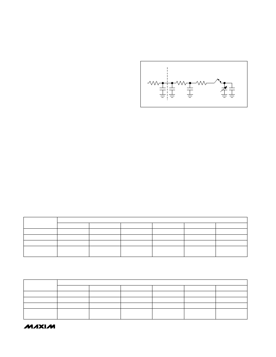
When used in unbuffered mode (BUFF = 0), the analog
inputs present a dynamic load to the driving circuitry.
The size of the sampling capacitor and the input sam-
pling frequency (Figure 5) determine the dynamic load
seen by the driving circuitry. The MAX1403 samples at a
constant rate for all gain settings. This provides a maxi-
mum time for the input to settle at a given data rate. The
dynamic load presented by the inputs varies with the
gain setting. For gains of +2V/V, +4V/V, and +8V/V, the
input sampling capacitor increases with the chosen
gain. Gains of +16V/V, +32V/V, +64V/V, and +128V/V
present the same input load as the x8 gain setting.
When designing with the MAX1403, as with any other
switched-capacitor ADC input, consider the advantages
and disadvantages of series input resistance. A series
resistor reduces the transient-current impulse to the
external driving amplifier. This improves the amplifier
phase margin and reduces the possibility of ringing.
The resistor spreads the transient-load current from the
sampler over time due to the RC time constant of the
circuit. However, an improperly chosen series resis-
tance can hinder performance in fast 16-bit converters.
The settling time of the RC network can limit the speed
at which the converter can operate properly, or reduce
the settling accuracy of the sampler. In practice, this
means ensuring that the RC time constant—resulting
from the product of the driving source impedance and
the capacitance presented by both the MAX1403’s
input and any external capacitances—is sufficiently
small to allow settling to the desired accuracy. Tables
13a–13d summarize the maximum allowable series
resistance vs. external capacitance for each MAX1403
gain setting in order to ensure 16-bit performance in
unbuffered mode.
MAX1403
+3V, 18-Bit, Low-Power, Multichannel,
Oversampling (Sigma-Delta) ADC
______________________________________________________________________________________
23
REXT
CEXT
RMUX
CPIN
RSW
CST
CSAMPLE
CC
Figure 5. Analog Input, Unbuffered Mode (BUFF = 0)
Table 13a. REXT, CEXT Values for Less than 16-Bit Gain Error in Unbuffered (BUFF = 0)
Mode—1x Modulator Sampling Frequency (MF1, MF0 = 00); X2CLK = 0; CLKIN = 2.4576MHz
Table 13b. REXT, CEXT Values for Less than 16-Bit Gain Error in Unbuffered (BUFF = 0)
Mode—2x Modulator Sampling Frequency (MF1, MF0 = 01); X2CLK = 0; CLKIN =
2.4576MHz
34
15
34
15
9.8
2
25
13
17
10
7.3
8, 16, 32,
64, 128
8.7
9.8
4
1
CEXT = 0pF
CEXT = 50pF
CEXT = 100pF
2.9
1.6
2.9
1.6
0.43
2.7
1.5
2.4
1.4
0.37
0.40
PGA GAIN
0.43
CEXT = 500pF
CEXT = 1000pF
CEXT = 5000pF
EXTERNAL RESISTANCE, REXT (k
)
17
7.5
17
7.5
4.9
2
13
6.4
8.4
5.0
3.7
8, 16, 32,
64, 128
4.4
4.9
4
1
CEXT = 0pF
CEXT = 50pF
CEXT = 100pF
1.4
0.81
1.4
0.81
0.22
1.3
0.76
1.2
0.70
0.18
0.20
PGA GAIN
0.22
CEXT = 500pF
CEXT = 1000pF
CEXT = 5000pF
EXTERNAL RESISTANCE, REXT (k
)
相關(guān)PDF資料 |
PDF描述 |
|---|---|
| AD586KRZ-REEL7 | IC VREF SERIES PREC 5V 8-SOIC |
| MAX1280EVC16 | EVAL KIT FOR MAX1280 |
| LGU2G221MELA | CAP ALUM 220UF 400V 20% SNAP |
| MAX1284EVC16 | EVALUATION SYSTEM FOR MAX1284 |
| 381LX682M025J012 | CAP ALUM 6800UF 25V 20% SNAP |
相關(guān)代理商/技術(shù)參數(shù) |
參數(shù)描述 |
|---|---|
| MAX1403EVSYSTEM | 制造商:Maxim Integrated Products 功能描述:EVALUATION SYSTEM FOR THE MAX1403 - Boxed Product (Development Kits) |
| MAX1406C/D | 功能描述:RS-232接口集成電路 RoHS:否 制造商:Exar 數(shù)據(jù)速率:52 Mbps 工作電源電壓:5 V 電源電流:300 mA 工作溫度范圍:- 40 C to + 85 C 安裝風(fēng)格:SMD/SMT 封裝 / 箱體:LQFP-100 封裝: |
| MAX1406CAE | 功能描述:RS-232接口集成電路 RoHS:否 制造商:Exar 數(shù)據(jù)速率:52 Mbps 工作電源電壓:5 V 電源電流:300 mA 工作溫度范圍:- 40 C to + 85 C 安裝風(fēng)格:SMD/SMT 封裝 / 箱體:LQFP-100 封裝: |
| MAX1406CAE+ | 功能描述:RS-232接口集成電路 15kV ESD-Protected 230kbps RS-232 LD/Rc RoHS:否 制造商:Exar 數(shù)據(jù)速率:52 Mbps 工作電源電壓:5 V 電源電流:300 mA 工作溫度范圍:- 40 C to + 85 C 安裝風(fēng)格:SMD/SMT 封裝 / 箱體:LQFP-100 封裝: |
| MAX1406CAE+T | 功能描述:RS-232接口集成電路 15kV ESD-Protected 230kbps RS-232 LD/Rc RoHS:否 制造商:Exar 數(shù)據(jù)速率:52 Mbps 工作電源電壓:5 V 電源電流:300 mA 工作溫度范圍:- 40 C to + 85 C 安裝風(fēng)格:SMD/SMT 封裝 / 箱體:LQFP-100 封裝: |
發(fā)布緊急采購(gòu),3分鐘左右您將得到回復(fù)。