- 您現(xiàn)在的位置:買賣IC網(wǎng) > PDF目錄358765 > LC78628E (Sanyo Electric Co.,Ltd.) 16-bit fixed point DSP with Flash PDF資料下載
參數(shù)資料
| 型號: | LC78628E |
| 廠商: | Sanyo Electric Co.,Ltd. |
| 元件分類: | 數(shù)字信號處理 |
| 英文描述: | 16-bit fixed point DSP with Flash |
| 中文描述: | 具有閃存的 16 位定點 DSP |
| 文件頁數(shù): | 31/40頁 |
| 文件大小: | 241K |
| 代理商: | LC78628E |
第1頁第2頁第3頁第4頁第5頁第6頁第7頁第8頁第9頁第10頁第11頁第12頁第13頁第14頁第15頁第16頁第17頁第18頁第19頁第20頁第21頁第22頁第23頁第24頁第25頁第26頁第27頁第28頁第29頁第30頁當前第31頁第32頁第33頁第34頁第35頁第36頁第37頁第38頁第39頁第40頁
Another point here is that these pins can be independently set to be used as control output pins with the PORT I/O set
command. The ports are selected with the lower 5 bits of the one byte of data. The one byte of data corresponds to
P0, P1, P2, P3, and P4 starting with the low order bit. This command has the two-byte command format (RWC set
once).
dn = 1 ... Sets Pn to be an output pin.
dn = 0 ... Sets Pn to be an input pin.
n = 0 to 4
No. 6329-31/40
LC78628E
One data byte + $DB
PORT I/O SET
Ports set up to be output pins can independently output either a high or low level. The low order 5 bits of the one byte
of data correspond to those ports. The one byte of data corresponds to P0, P1, P2, P3, and P4 starting with the low
order bit. This command has the two-byte command format (RWC set once).
dn = 1 ... Outputs a high level from Pn, which is set up for output.
dn = 0 ... Outputs a low level from Pn, which is set up for output.
n = 0 to 4
One data byte + $DC
PORT OUTPUT SET
19. Clock oscillator — Pin 43: XIN, pin 4: XOUT
20. 16M and 4.2M pins — Pin 30: 16M, pin 72: 4.2M
The 16M pin outputs the 16.9344 MHz clock which is output of the buffer for the 16.9344 MHz crystal oscillator.
The 4.2M pin outputs a 4.2336 MHz clock signal which can be used as the system clock for an LA9230/40 Series IC.
When the oscillator is turned off both these pins will be fixed at either high or low.
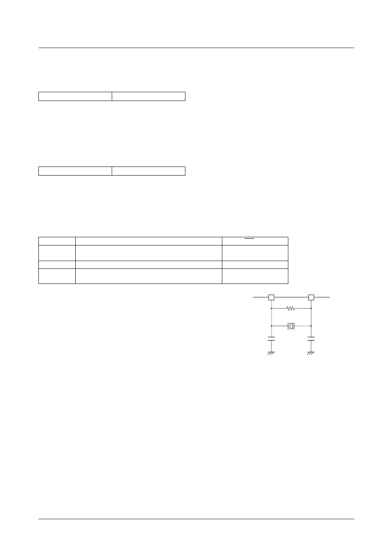
The clock that is used as the time base is generated by connecting a 16.9344
MHz oscillator element between these pins. The OSC OFF command turns
off both the VCO and crystal oscillators.
When implementing a system that supports double-speed playback, the
playback speed is set with either the double-speed playback command or
the normal speed playback command.
Recommended oscillator element: CSA-309 (Citizen Watch Co., Ltd.)
SCA16.93MXZ040 (Toyama Murata Mfg. Co., Ltd.)
The oscillator circuit should be located as close as possible to the IC. We
recommend evaluating oscillator performance on the printed circuit board
actually used to determine the values of the resistor (Rf) and capacitors (C)
used.
Code
Command
RES = low
$8E
OSC ON
G
G
$8D
OSC OFF
$CE
XTAL 16M
G
G
$C2
Normal-speed playback
G
G
$C1
Double-speed playback
XOUT
Rf
Oscillator
element
44
43
C
C
XIN
A12833
相關(guān)PDF資料 |
PDF描述 |
|---|---|
| LC78630 | 16-bit fixed point DSP with Flash |
| LC78630E | 16-bit fixed point DSP with Flash |
| LC78631 | 16-bit fixed point DSP with Flash |
| LC78631E | 16-bit fixed point DSP with Flash |
| LC78632 | 16-bit fixed point DSP with Flash |
相關(guān)代理商/技術(shù)參數(shù) |
參數(shù)描述 |
|---|---|
| LC7863 | 制造商:SANYO 制造商全稱:Sanyo Semicon Device 功能描述:DIGITAL SIGNAL PROCESSOR FOR COMPACT DISC PLAYERS |
| LC78630 | 制造商:SANYO 制造商全稱:Sanyo Semicon Device 功能描述:Compact Disk Player DSP |
| LC78630E | 制造商:SANYO 制造商全稱:Sanyo Semicon Device 功能描述:Compact Disk Player DSP |
| LC78631 | 制造商:SANYO 制造商全稱:Sanyo Semicon Device 功能描述:Compact Disk Player DSP |
| LC78631E | 制造商:SANYO 制造商全稱:Sanyo Semicon Device 功能描述:Compact Disk Player DSP |
發(fā)布緊急采購,3分鐘左右您將得到回復(fù)。