- 您現(xiàn)在的位置:買賣IC網(wǎng) > PDF目錄43901 > L7250 (STMICROELECTRONICS) VOICE COIL MOTOR CONTROLLER, PQFP64 PDF資料下載
參數(shù)資料
| 型號: | L7250 |
| 廠商: | STMICROELECTRONICS |
| 元件分類: | 運動控制電子 |
| 英文描述: | VOICE COIL MOTOR CONTROLLER, PQFP64 |
| 封裝: | TQFP-64 |
| 文件頁數(shù): | 16/46頁 |
| 文件大小: | 478K |
| 代理商: | L7250 |
第1頁第2頁第3頁第4頁第5頁第6頁第7頁第8頁第9頁第10頁第11頁第12頁第13頁第14頁第15頁當前第16頁第17頁第18頁第19頁第20頁第21頁第22頁第23頁第24頁第25頁第26頁第27頁第28頁第29頁第30頁第31頁第32頁第33頁第34頁第35頁第36頁第37頁第38頁第39頁第40頁第41頁第42頁第43頁第44頁第45頁第46頁
23/46
L7250
Sense, to determine rotor position, Open Loop Commutation, which accelerates the motor to build up BEMF,
Synchronization , to measure motor speed and position, initializing the Smoothdrive system, and Closed Loop
Smoothdrive Commutation, the normal synchronous commutation mode to accelerate and run at speed.
2.7.1 Inductive Position Sense
Inductive position sensing is achieved through a firmware routine that measures the current rise time in each of
the six possible states (six steps profile), and uses this information to determine the rotor position.
The six steps profile still comes from the Profile Memory that contains 48 samples, but in this case there are
only six different configuration, each of them repeated eight times; the linear scansion of the memory one sam-
ple at a time gives a new six step configuration every eight increments.
Before any operation can be done, the firmware routine must set the KVAL value present in SPI to the maximum
value (*1) , to saturate the PWM signals given to the motor, and put the Memory Address Counter in a known
position (*3); this is done keeping the motor in OLCOAST (*2) state and asserting a LoadCP command (*4) to
load the content of the torque optimizer related SPI register into the Memory Address Counter.
At this point, the present six steps configuration can be energized through the INDSENSE state (*5) , waiting
for the current to reach the threshold programmable via SPI (*6); the current limiting comparator will be triggered
by this condition, and it's output will be visible at ZC pad. The current rise time will be measured and stored from
the ASIC (*7) .
The device automatically limits the PWM signals for the three phases to limit the current, but the currents in the
windings must be recirculated from firmware putting the motor in OLCOAST (*8) state.
A burst of eight ADVANCE signals (*9) must be asserted from SPI to reach the next configuration in the profile
memory, then the procedure can be repeated. Each winding can be excited more than one time, to average the
measurements, and at the end of the sensing sequence the ASIC decides the rotor position.
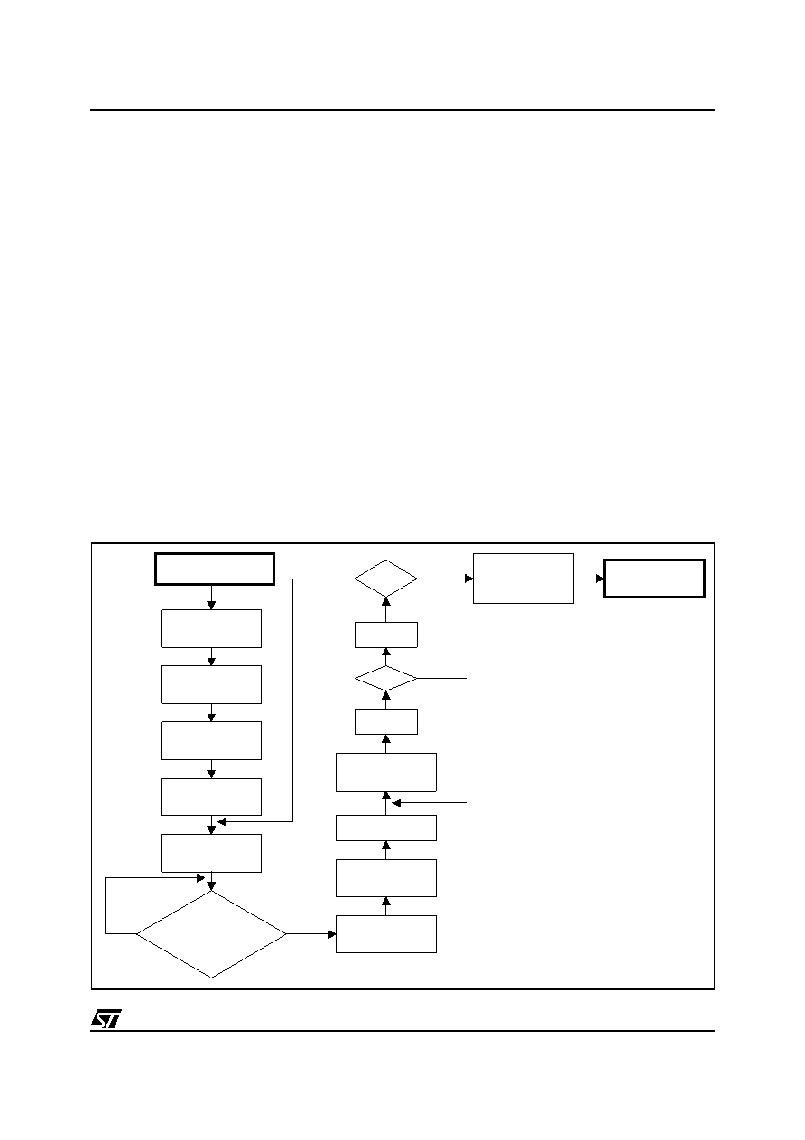
Figure 4. Inductive Sense Routine
Set KVAL
Write Reg.08H
Kv[7:0] = 11111111
Measure Current
Rise Time
By reading the
ZC (pin 22)
Set OLCOAST
Write Reg.03H
Spstate[3:0] = 0001
Set Torque Optimizer
Write Reg.07H
TO[4:0] = 00000
Set Load Coarse Phase
Write Reg.07H
LoadCP = 1
Set ADVANCE
Write Reg.07H
Advance = 1
Set INDUCTIVE SENSE
Write Reg.03H
Spstate[3:0] = 0101
Store the measured
Current Rise Time
& Nph associated
Set OLCOAST
Write Reg.03H
Spstate[3:0] = 0001
START
Inductive Sense Routine
Nadv=0 , Nph=0
Nadv=8
Inc Nadv
Inc Nph
Nph
= 48
Compare the Six
Measured Rise Time
to define the
ROTOR POSITION
EXIT
Inductive Sense
Routine
Wait for
Current Decay
Nadv=0
ZC=0
ZC=1
NO
YES
NO
(*1)
(*2)
(*3)
(*4)
(*5)
(*6)
(*7)
(*8)
(*9)
相關(guān)PDF資料 |
PDF描述 |
|---|---|
| L7980A | 3.5 A SWITCHING REGULATOR, 1000 kHz SWITCHING FREQ-MAX, PDSO8 |
| L7980 | 3.5 A SWITCHING REGULATOR, 1000 kHz SWITCHING FREQ-MAX, PDSO8 |
| L7980TR | 3.5 A SWITCHING REGULATOR, 1000 kHz SWITCHING FREQ-MAX, PDSO8 |
| L7981ATR | SWITCHING REGULATOR, DSO8 |
| L7981TR | SWITCHING REGULATOR, DSO8 |
相關(guān)代理商/技術(shù)參數(shù) |
參數(shù)描述 |
|---|---|
| L7250E1.2 | 功能描述:電源開關(guān) IC - 配電 DSD POWER RoHS:否 制造商:Exar 輸出端數(shù)量:1 開啟電阻(最大值):85 mOhms 開啟時間(最大值):400 us 關(guān)閉時間(最大值):20 us 工作電源電壓:3.2 V to 6.5 V 電源電流(最大值): 最大工作溫度:+ 85 C 安裝風格:SMD/SMT 封裝 / 箱體:SOT-23-5 |
| L7252E2.6 | 功能描述:電源開關(guān) IC - 配電 DSD POWER RoHS:否 制造商:Exar 輸出端數(shù)量:1 開啟電阻(最大值):85 mOhms 開啟時間(最大值):400 us 關(guān)閉時間(最大值):20 us 工作電源電壓:3.2 V to 6.5 V 電源電流(最大值): 最大工作溫度:+ 85 C 安裝風格:SMD/SMT 封裝 / 箱體:SOT-23-5 |
| L725MAG | 制造商:Apex Tool Group 功能描述:TAPE, 1 IN. X 25 FT, 700 SERIES, MAGNETIC END HOOK 制造商:Lufkin 功能描述:TAPE MEASURE, MAGNETIC END HOOK 25FT 1IN; Tape Measure Type:Manual; Measuring Range Max:25ft; Blade Width:1"; Case Color:Orange; Tool Body Material:ABS; Blade Finish:Yellow Clad; Blade Length:25ft ;RoHS Compliant: NA |
| L728 | 制造商:BURNDY 功能描述:L-DIE |
| L7290 | 制造商:CIPS 功能描述:CUTTER OBLIQUE SEMI FLUSH 109MM |
發(fā)布緊急采購,3分鐘左右您將得到回復(fù)。