- 您現(xiàn)在的位置:買賣IC網(wǎng) > PDF目錄384585 > L6711 (意法半導(dǎo)體) 3 PHASE CONTROLLER WITH DYNAMIC VID AND SELECTABLE DACs PDF資料下載
參數(shù)資料
| 型號(hào): | L6711 |
| 廠商: | 意法半導(dǎo)體 |
| 英文描述: | 3 PHASE CONTROLLER WITH DYNAMIC VID AND SELECTABLE DACs |
| 中文描述: | 3相控制器,動(dòng)態(tài)VID和可選數(shù)模轉(zhuǎn)換器 |
| 文件頁(yè)數(shù): | 4/38頁(yè) |
| 文件大?。?/td> | 591K |
| 代理商: | L6711 |
第1頁(yè)第2頁(yè)第3頁(yè)當(dāng)前第4頁(yè)第5頁(yè)第6頁(yè)第7頁(yè)第8頁(yè)第9頁(yè)第10頁(yè)第11頁(yè)第12頁(yè)第13頁(yè)第14頁(yè)第15頁(yè)第16頁(yè)第17頁(yè)第18頁(yè)第19頁(yè)第20頁(yè)第21頁(yè)第22頁(yè)第23頁(yè)第24頁(yè)第25頁(yè)第26頁(yè)第27頁(yè)第28頁(yè)第29頁(yè)第30頁(yè)第31頁(yè)第32頁(yè)第33頁(yè)第34頁(yè)第35頁(yè)第36頁(yè)第37頁(yè)第38頁(yè)
L6711
4/38
11
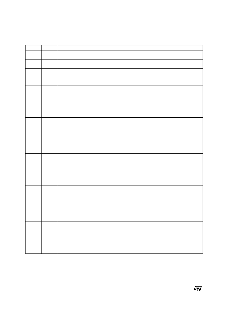
FBR
Remote sense buffer non-inverting input.
It has to be connected to the positive side of the load to perform a remote sense.
Remote sense buffer inverting input.
It has to be connected to the negative side of the load to perform a remote sense.
Output Enable pin, internally 3V pulled-up.
If forced to a voltage lower than 0.3V, the device stops operation with all mosfets OFF: all the
protections are disabled in this condition except pre-OVP.
Cycle this pin to recover latch from protections; filter with 1nF (Typ.) capacitor vs. SGND.
Channel 1 Current Sense Negative Input pin.
It must be connected through an Rg resistor to the LS mosfet drain (or to the LS-side of the
sense resistor placed in series to the LS mosfet) if LS mosfet sense is performed
(CS_SEL=OPEN). Otherwise (CS_SEL=SGND), it must be connected to the output-side of the
output inductor (or the output-side of the sense resistor used and placed between the channel 1
inductor and the output of the converter) through Rg resistor.
The net connecting the pin to the sense point must be routed as close as possible to the CS1+
net in order to couple in common mode any picked-up noise.
Channel 1 Current Sense Positive Input pin.
It must be connected through an Rg resistor to the LS mosfet source (or to the GND-side of the
sense resistor placed in series to the LS mosfet) if LS mosfet sense is performed
(CS_SEL=OPEN). Otherwise (CS_SEL=SGND), it must be connected to the phase-side of the
output inductor (or the inductor-side of the sense resistor used and placed between the channel
1 inductor and the output of the converter) through Rg resistor and an R-C network across the
inductor.
The net connecting the pin to the sense point must be routed as close as possible to the CS1-
net in order to couple in common mode any picked-up noise.
Channel 2 Current Sense Negative Input pin.
It must be connected through an Rg resistor to the LS mosfet drain (or to the LS-side of the
sense resistor placed in series to the LS mosfet) if LS mosfet sense is performed
(CS_SEL=OPEN). Otherwise (CS_SEL=SGND), it must be connected to the output-side of the
output inductor (or the output-side of the sense resistor used and placed between the channel 2
inductor and the output of the converter) through Rg resistor.
The net connecting the pin to the sense point must be routed as close as possible to the CS2+
net in order to couple in common mode any picked-up noise.
Channel 2 Current Sense Positive Input pin.
It must be connected through an Rg resistor to the LS mosfet source (or to the GND-side of the
sense resistor placed in series to the LS mosfet) if LS mosfet sense is performed
(CS_SEL=OPEN). Otherwise (CS_SEL=SGND), it must be connected to the phase-side of the
output inductor (or the inductor-side of the sense resistor used and placed between the channel
2 inductor and the output of the converter) through Rg resistor and an R-C network across the
inductor.
The net connecting the pin to the sense point must be routed as close as possible to the CS2-
net in order to couple in common mode any picked-up noise.
Channel 3 Current Sense Negative Input pin.
It must be connected through an Rg resistor to the LS mosfet drain (or to the LS-side of the
sense resistor placed in series to the LS mosfet) if LS mosfet sense is performed
(CS_SEL=OPEN). Otherwise (CS_SEL=SGND), it must be connected to the output-side of the
output inductor (or the output-side of the sense resistor used and placed between the channel 3
inductor and the output of the converter) through Rg resistor.
The net connecting the pin to the sense point must be routed as close as possible to the CS3+
net in order to couple in common mode any picked-up noise.
12
FBG
13
OUTEN
14
CS1-
15
CS1+
16
CS2-
17
CS2+
18
CS3-
Table 4. Pin Function
(continued)
N°
Name
Description
相關(guān)PDF資料 |
PDF描述 |
|---|---|
| L6711TR | 3 PHASE CONTROLLER WITH DYNAMIC VID AND SELECTABLE DACs |
| L6714 | 4 phase controller with embedded drivers for Intel VR10, VR11 and AMD 6Bit CPUs |
| L6714TR | 4 phase controller with embedded drivers for Intel VR10, VR11 and AMD 6Bit CPUs |
| L6726A | Single phase PWM controller |
| L6726ATR | Single phase PWM controller |
相關(guān)代理商/技術(shù)參數(shù) |
參數(shù)描述 |
|---|---|
| L6711_06 | 制造商:STMICROELECTRONICS 制造商全稱:STMicroelectronics 功能描述:3 Phase controller with dynamic VID and selectable DACs |
| L6711TR | 功能描述:DC/DC 開(kāi)關(guān)控制器 3 PHASE CONTROLLER RoHS:否 制造商:Texas Instruments 輸入電壓:6 V to 100 V 開(kāi)關(guān)頻率: 輸出電壓:1.215 V to 80 V 輸出電流:3.5 A 輸出端數(shù)量:1 最大工作溫度:+ 125 C 安裝風(fēng)格: 封裝 / 箱體:CPAK |
| L6712 | 制造商:STMICROELECTRONICS 制造商全稱:STMicroelectronics 功能描述:TWO-PHASE INTERLEAVED DC/DC CONTROLLER |
| L6712_05 | 制造商:STMICROELECTRONICS 制造商全稱:STMicroelectronics 功能描述:TWO-PHASE INTERLEAVED DC/DC CONTROLLER |
| L6712A | 制造商:STMICROELECTRONICS 制造商全稱:STMicroelectronics 功能描述:TWO-PHASE INTERLEAVED DC/DC CONTROLLER |
發(fā)布緊急采購(gòu),3分鐘左右您將得到回復(fù)。