- 您現(xiàn)在的位置:買賣IC網(wǎng) > PDF目錄369586 > KP80524NY450128 Microprocessor PDF資料下載
參數(shù)資料
| 型號(hào): | KP80524NY450128 |
| 英文描述: | Microprocessor |
| 中文描述: | 微處理器 |
| 文件頁(yè)數(shù): | 28/81頁(yè) |
| 文件大小: | 598K |
| 代理商: | KP80524NY450128 |
第1頁(yè)第2頁(yè)第3頁(yè)第4頁(yè)第5頁(yè)第6頁(yè)第7頁(yè)第8頁(yè)第9頁(yè)第10頁(yè)第11頁(yè)第12頁(yè)第13頁(yè)第14頁(yè)第15頁(yè)第16頁(yè)第17頁(yè)第18頁(yè)第19頁(yè)第20頁(yè)第21頁(yè)第22頁(yè)第23頁(yè)第24頁(yè)第25頁(yè)第26頁(yè)第27頁(yè)當(dāng)前第28頁(yè)第29頁(yè)第30頁(yè)第31頁(yè)第32頁(yè)第33頁(yè)第34頁(yè)第35頁(yè)第36頁(yè)第37頁(yè)第38頁(yè)第39頁(yè)第40頁(yè)第41頁(yè)第42頁(yè)第43頁(yè)第44頁(yè)第45頁(yè)第46頁(yè)第47頁(yè)第48頁(yè)第49頁(yè)第50頁(yè)第51頁(yè)第52頁(yè)第53頁(yè)第54頁(yè)第55頁(yè)第56頁(yè)第57頁(yè)第58頁(yè)第59頁(yè)第60頁(yè)第61頁(yè)第62頁(yè)第63頁(yè)第64頁(yè)第65頁(yè)第66頁(yè)第67頁(yè)第68頁(yè)第69頁(yè)第70頁(yè)第71頁(yè)第72頁(yè)第73頁(yè)第74頁(yè)第75頁(yè)第76頁(yè)第77頁(yè)第78頁(yè)第79頁(yè)第80頁(yè)第81頁(yè)

Mobile Intel
Celeron Processor (0.18μ) in BGA2 and Micro-PGA2 Packages
Datasheet
Order Number#249563-001
28
Table 15 contains the GTL+ specifications; Table 16 contains the CMOS and Open-drain signal
groups specifications; Table 17 contains timings for the reset conditions; Table 18 contains the
APIC specifications; Table 19 contains the TAP specifications; and Table 20 and Table 21 contain
the power management timing specifications.
All system bus AC specifications for the GTL+ signal group are relative to the rising edge of the
BCLK input at 1.25V. All GTL+ timings are referenced to V
REF
for both “0” and “1” logic levels
unless otherwise specified. All APIC, TAP, CMOS, and Open-drain signals except PWRGOOD
are referenced to 0.75V.
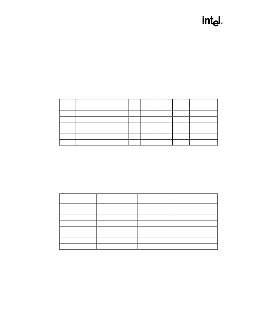
Table 13. System Bus Clock AC Specifications
1
T
J
= 0°C to 100°C; V
CC
= 1.10V ±80 mV or 1.35V ±100 mV or 1.60V ±115 mV; V
CCT
= 1.50V ±115 mV
Symbol
Parameter
Min
Typ
Max
Unit
Figure
Notes
System Bus Frequency
100
MHz
T1
BCLK Period
10
ns
Figure 6
Note 2
T2
BCLK Period Stability
±250
ps
Notes 3, 4
T3
BCLK High Time
2.70
ns
Figure 6
at >2.0V
T4
BCLK Low Time
2.45
ns
Figure 6
at <0.5V
T5
BCLK Rise Time
0.175
0.875
ns
Figure 6
(0.9V – 1.6V)
T6
BCLK Fall Time
0.175
0.875
ns
Figure 6
(1.6V – 0.9V)
NOTES:
1.
All AC timings for GTL+ and CMOS signals are referenced to the BCLK rising edge at 1.25V. All CMOS
signals are referenced at 0.75V.
The BCLK period allows a +0.5 ns tolerance for clock driver variation.
Not 100% tested. Specified by design/characterization.
Measured on the rising edge of adjacent BCLKs at 1.25V. The jitter present must be accounted for as a
component of BCLK skew between devices.
2.
3.
4.
Table 14. Valid Mobile Intel Celeron Processor Frequencies
T
J
= 0°C to 100°C; V
CC
= 1.10V ±80 mV or 1.35V ±100 mV or 1.60V ±115 mV; V
CCT
= 1.50V ±115 mV
BCLK Frequency
(MHz)
Frequency Multiplier
Core Frequency
(MHz)
Power-on Configuration
bits [27, 25:22]
100
4.0
400A
0, 0010
100
4.5
450
0, 0110
100
5.0
500
0, 0000
100
5.5
550
0, 0100
100
6.0
600
0, 1011
100
6.5
650
0, 1111
100
7.0
700
0, 1001
100
7.5
750
0, 1101
NOTE:
While other combinations of bus and core frequencies are defined, operation at frequencies other
than those listed above will not be validated by Intel and are not guaranteed. The frequency multiplier
is programmed into the processor when it is manufactured and it cannot be changed.
相關(guān)PDF資料 |
PDF描述 |
|---|---|
| RH8053GC017512 | Microprocessor |
| RH8053GC021512 | Microprocessor |
| RH8053GC025512 | Microprocessor |
| RH8053GC029512 | Microprocessor |
| RH8053GC033512 | Microprocessor |
相關(guān)代理商/技術(shù)參數(shù) |
參數(shù)描述 |
|---|---|
| KP80526NY700128 | 制造商:Rochester Electronics LLC 功能描述:- Bulk 制造商:Intel 功能描述: |
| KP80S 3601F200 | 制造商:STKE 功能描述: |
| KP80S 3602F100 | 制造商:STKE 功能描述: |
| KP80S1801F100 | 制造商:STK ELECTRONICS 功能描述: |
| KP80S2202J600 | 制造商:n/a 功能描述:AF322X600 5% |
發(fā)布緊急采購(gòu),3分鐘左右您將得到回復(fù)。