- 您現(xiàn)在的位置:買賣IC網(wǎng) > PDF目錄385396 > HSP50214VI (INTERSIL CORP) Programmable Downconverter PDF資料下載
參數(shù)資料
| 型號(hào): | HSP50214VI |
| 廠商: | INTERSIL CORP |
| 元件分類: | 通信及網(wǎng)絡(luò) |
| 英文描述: | Programmable Downconverter |
| 中文描述: | SPECIALTY TELECOM CIRCUIT, PQFP120 |
| 封裝: | MQFP-120 |
| 文件頁數(shù): | 43/54頁 |
| 文件大小: | 395K |
| 代理商: | HSP50214VI |
第1頁第2頁第3頁第4頁第5頁第6頁第7頁第8頁第9頁第10頁第11頁第12頁第13頁第14頁第15頁第16頁第17頁第18頁第19頁第20頁第21頁第22頁第23頁第24頁第25頁第26頁第27頁第28頁第29頁第30頁第31頁第32頁第33頁第34頁第35頁第36頁第37頁第38頁第39頁第40頁第41頁第42頁當(dāng)前第43頁第44頁第45頁第46頁第47頁第48頁第49頁第50頁第51頁第52頁第53頁第54頁
43
7-4
Loop Gain 0 Mantissa
Selected when AGCGNSEL = 0. These bits are MMMM. See description for bits 15-12. Same
equations are used for Loop 0. Bit 7 is the MSB.
3-0
Loop Gain 0
Exponent
Selected when AGCGNSEL = 0. These bits are EEEE. See description for bits 15-12. Same
equations are used for Loop 0. Bit 3 is the MSB.
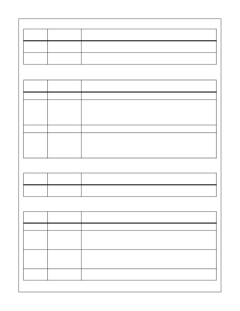
CONTROL WORD 9: AGC CONFIGURATION 2 (SYNCHRONIZED TO PROCCLK)
BIT
POSITION
FUNCTION
DESCRIPTION
31-28
Reserved
Reserved
27-16
Upper Limit
Maximum gain/minimum signal. The upper four bits are used for exponent; the remaining bits
form the mantissa in the fractional offset binary: [eeeemmmmmmmm]. See the AGC Section for
details. Bit 27 is the MSB. The gain is in dB. G = (6.02)(eeee) + 20log
10
(1.0 + 0.mmmmmmmm)
eeee = Floor [log
2
(10
GAIN dB/20
)].
mmmmmmmm = Floor [512(10
GAIN dB/20
/2
eeee
- 1)].
15-12
Reserved
Reserved.
11-0
Lower Limit
Minimum gain/maximum signal. The upper four bits are used for exponent; the remaining bits
form the mantissa in the fractional offset binary: [eeeemmmmmmmm]. See the AGC Section for
details. Bit 11 is the MSB. The gain is in dB. G = (6.02)(eeee) + 20log
10
(1.0 + 0.mmmmmmmm).
eeee = Floor [log
2
(10
GAIN dB/20
)].
mmmmmmmm = Floor [512(10
GAIN dB/20
/2
eeee
- 1)].
CONTROL WORD 10: AGC SAMPLE GAIN CONTROL STROBE (SYNCHRONIZED TO PROCCLK)
BIT
POSITION
FUNCTION
DESCRIPTION
N/A
Sample AGC Gain
Level
Writing to this location samples the output of the AGC loop filter to stabilize the value for
μ
P
reading.
CONTROL WORD 11: TIMING NCO CONFIGURATION (SYNCHRONIZED TO PROCCLK)
BIT
POSITION
FUNCTION
DESCRIPTION
31-6
Reserved
Reserved.
5
Enable External
Timing NCO Sync
0- SYNCIN2 has no effect on the timing NCO.
1- When SYNCIN2 is asserted, the timing NCO center frequency and phase are updated with
the value loaded in their holding registers. If bit 0 of this word is set to 1, the phase accumulator
feedback is also zeroed.
4-3
Number of Offset
Frequency Bits
00 - 8 bits.
01 - 16.
10 - 24.
11 - 32.
2
Enable Offset
Frequency
0- Zero Offset Frequency to Adder.
1- Enable Offset Frequency.
CONTROL WORD 8: AGC CONFIGURATION 1 (SYNCHRONIZED TO PROCCLK)
BIT
POSITION
FUNCTION
DESCRIPTION
HSP50214
相關(guān)PDF資料 |
PDF描述 |
|---|---|
| HSP50214 | Programmable Downconverter |
| HSP50215VC | Digital UpConverter |
| HSP50215VI | Digital UpConverter |
| HSP50215EVAL | DSP Modulator Evaluation Board |
| HSP50215 | Digital UpConverter(數(shù)字上變頻器) |
相關(guān)代理商/技術(shù)參數(shù) |
參數(shù)描述 |
|---|---|
| HSP50215 | 制造商:INTERSIL 制造商全稱:Intersil Corporation 功能描述:DSP Modulator Evaluation Board |
| HSP50215EVAL | 制造商:INTERSIL 制造商全稱:Intersil Corporation 功能描述:DSP Modulator Evaluation Board |
| HSP50215VC | 制造商:INTERSIL 制造商全稱:Intersil Corporation 功能描述:Digital UpConverter |
| HSP50215VI | 制造商:INTERSIL 制造商全稱:Intersil Corporation 功能描述:Digital UpConverter |
| HSP50216 | 制造商:INTERSIL 制造商全稱:Intersil Corporation 功能描述:Four-Channel Programmable Digital Downconverter |
發(fā)布緊急采購(gòu),3分鐘左右您將得到回復(fù)。