- 您現(xiàn)在的位置:買賣IC網(wǎng) > PDF目錄370499 > HDMP-1526 Transistor Diode Kit;Contents Of Kit:Transistor/Diode Kit PDF資料下載
參數(shù)資料
| 型號(hào): | HDMP-1526 |
| 英文描述: | Transistor Diode Kit;Contents Of Kit:Transistor/Diode Kit |
| 中文描述: | 光纖通道收發(fā)器芯片 |
| 文件頁(yè)數(shù): | 13/14頁(yè) |
| 文件大小: | 229K |
| 代理商: | HDMP-1526 |
第1頁(yè)第2頁(yè)第3頁(yè)第4頁(yè)第5頁(yè)第6頁(yè)第7頁(yè)第8頁(yè)第9頁(yè)第10頁(yè)第11頁(yè)第12頁(yè)當(dāng)前第13頁(yè)第14頁(yè)
694
Transceiver Package
Information
The HDMP-1526 is constructed
of a single integrated circuit
packaged in a 14x14 mm
EDQuad package. This package
was designed to provide
enhanced power dissipation, thus
allowing for smaller package
dimensions. The package
conforms to the industry standard
JEDEC land pattern for 14x14
mm devices. As shown in Figure
12, the die is attached to a
copper heatsink using thermally
conductive epoxy. This allows for
the power dissipated by the IC to
be directly connected to the
ambient environment, thereby
minimizing the
Θ
jc of the device.
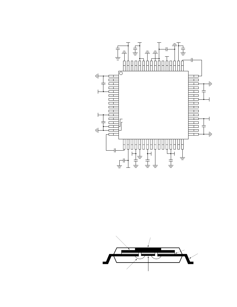
Figure 12. Power Supply Bypass.
RXCAP0
V
CC
_RXTTL
V
CC
_RXTTL
G
TOP VIEW
GND_RXTTL
GND_TXTTL
V
CC
_TXTTL
V
CC
_TXTTL
GND_TXTTL
GND_TXA
TXCAP0
V
C
_
V
C
_
V
C
_
G
V
C
_
G
V
C
_
V
C
_
G
V
C
_
R
* SUPPLY VOLTAGE INTO V
_RXA AND V
_TXA SHOULD
BE FROM A LOW NOISE SOURCE. ALL BYPASS CAPACITORS
ARE 0.1 μF. THE PLL FILTER CAPACITORS ARE 0.01 μF.
V
C
_
G
V
CC
V
CC
V
CC
V
CC
*
V
CC
V
CC
V
CC
GND_RXTTL
T
V
C
_
G
V
C
_
G
V
C
_
V
C
_
V
CC
C
PLLT
V
CC
*
V
CC
V
CC
V
CC
V
CC
C
PLLR
Transceiver Power
Supply Bypass and Loop
Filter Capacitors
Bypass capacitors should be
liberally used and placed as close
as possible to the appropriate
power supply pins of the HDMP-
1526 as shown on the schematic
of Figure 11. All bypass chip
capacitors are 0.1
μ
F. The
VCC_RXA and VCC_TXA pins are
the analog power supply pins for
the PLL sections. The voltage into
these pins should be clean with
minimum noise. The PLL loop
filter capacitors and their pin
locations are also shown on
Figure 11. Notice that only two
capacitors are required: C
PLLT
for
the transmitter and C
PLLR
for the
receiver. Nominal capacitance is
0.01
μ
F. The voltage across the
capacitors is on the order of 1
volt, so the capacitor can be a
low voltage type and physically
small. The PLL capacitors are
placed physically close to the
appropriate pins on the HDMP-
1526. Keeping the lines short will
prevent them from picking up
stray noise from surrounding
lines or components.
COPPER HEATSINK
NICKEL PLATING
CERAMIC
LEAD
DIE
WIRE BOND
Figure 13. Package Cross Section of HDMP-1526.
相關(guān)PDF資料 |
PDF描述 |
|---|---|
| HDMP-1536 | Fibre Channel Transceiver Chip |
| HDMP-1546 | Fibre Channel Transceiver Chip |
| HDMP-1546A | Fibre Channel Transceiver Chip(光纖通道收發(fā)器芯片) |
| HDMP-1536A | Fibre Channel Transceiver Chip(光纖通道收發(fā)器芯片) |
| HDMP-1636 | Software |
相關(guān)代理商/技術(shù)參數(shù) |
參數(shù)描述 |
|---|---|
| HDMP-1536 | 制造商:AGILENT 制造商全稱:AGILENT 功能描述:Fibre Channel Transceiver Chip |
| HDMP-1536A | 制造商:未知廠家 制造商全稱:未知廠家 功能描述:Fiber-Optic Transceiver |
| HDMP-1546 | 制造商:AGILENT 制造商全稱:AGILENT 功能描述:Fibre Channel Transceiver Chip |
| HDMP-1546A | 制造商:未知廠家 制造商全稱:未知廠家 功能描述:IC-TRANSCEIVER |
| HDMP-1636 | 制造商:AGILENT 制造商全稱:AGILENT 功能描述:Gigabit Ethernet Transceiver Chip |
發(fā)布緊急采購(gòu),3分鐘左右您將得到回復(fù)。