- 您現(xiàn)在的位置:買賣IC網(wǎng) > PDF目錄375853 > FM8P51EF (Electronic Theatre Controls, Inc.) EPROM/ROM-Based 8-Bit Microcontroller PDF資料下載
參數(shù)資料
| 型號: | FM8P51EF |
| 廠商: | Electronic Theatre Controls, Inc. |
| 英文描述: | EPROM/ROM-Based 8-Bit Microcontroller |
| 中文描述: | 存儲器/基于ROM的8位微控制器 |
| 文件頁數(shù): | 27/60頁 |
| 文件大小: | 369K |
| 代理商: | FM8P51EF |
第1頁第2頁第3頁第4頁第5頁第6頁第7頁第8頁第9頁第10頁第11頁第12頁第13頁第14頁第15頁第16頁第17頁第18頁第19頁第20頁第21頁第22頁第23頁第24頁第25頁第26頁當(dāng)前第27頁第28頁第29頁第30頁第31頁第32頁第33頁第34頁第35頁第36頁第37頁第38頁第39頁第40頁第41頁第42頁第43頁第44頁第45頁第46頁第47頁第48頁第49頁第50頁第51頁第52頁第53頁第54頁第55頁第56頁第57頁第58頁第59頁第60頁

FM8P51
Rev1.2 Mar 15, 2005
P.27/FM8P51
FEELING
TECHNOLOGY
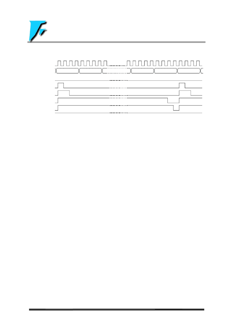
FIGURE 2.8: The Output Waveform of PWM Driver (PRx = N)
Fosc
TMRx
DCx = 0
DCx = 1
DCx = 2
DCx = N*4 + 2
DCx = N*4 + 3
DCx
≥
(N+1)*4
2.7 SPI(Serial Peripheral Interface) Module
The Serial Port Interface (SPI) Module is a serial interface useful communicating with other peripheral or
microcontroller device.
The SPI mode allows 8-bit of data to be synchronously transmitted and received simultaneously. To accomplish
communication, typically three pins are used:
1. Serial Clock (SCK)
2. Serial Data In (SDI)
3. Serial Data Output (SDO)
Additionally a fourth pin may be used when in a slave mode of operation:
4. Slave Select (SSB)
The SPI consists of a transmit/receive shift register (SPISR), a receive buffer register (SPIRCB), and a transmit
buffer register (SPITXB). The SPISR shifts the data in and out of the device, MSB first. Once the first valid clock
pulse appear on SCK pin (controlled by SSE (SPICON<4>) and SSEMOD (SPICON<3>) bits), data in SPITXB will
be loaded into SPISR and start to shift in/out, then transmit buffer empty detect bit TXBF (SPISTAT<5>), and
interrupt flag bits SPITXIF (INTFLAG<7>) and TXBFIF (SPISTAT<6>) are set. Once the 8-bits of data have been
received, the data in SPISR will be moved to the SPIRCB register, then receive buffer full detect bit RCBF
(SPISTAT<0>), and interrupt flag bits SPIRCIF (INTFLAG<2>) and RCBFIF (SPISTAT<1>) are set.
If FM8P51 is a master controller, it sends clock through the SCK pin. A couple of 8-bit data are transmitted and
received at the same time. And if FM8P51 is defined as a slave, its SCK pin could be programmed as an input pin.
Data will continue to be shifted based on both the clock rate and the selected edge.
When the application S/W is expecting to transmit valid data, the SPITXB should be write before the last byte of data
have been transmitted completely. Buffer empty bit TXBF indicates when SPISR has been loaded with the data of
SPITXB (reception/transmission start). The TXBF bit is cleared by software or by writting SPITXB register. And the
TXBF bit may be ignored if the SPI is only a receiver.
Also when the application S/W is expecting to receive valid data, the SPIRCB should be read before the next byte of
data have been received completely. Buffer full bit RCBF indicates when SPIRCB has been loaded with the
received data (reception/transmission is complete). The RCBF bit is cleared by software or by reading SPIRCB
register. And the RCBF bit may be ignored if the SPI is only a transmitter.
Generally the SPI interrupt is used to determine when the transmission/reception has started/completed, the
SPIRCB/SPITXB must be read and/or written. If the interrupt method is not going to be used, then S/W polling
RCBF and/or TXBF bits is needed.
If the SPI is only going to receive, the TXBF flag could be ignored.
0
1
N
0
N-1
相關(guān)PDF資料 |
PDF描述 |
|---|---|
| FM8P51EP | EPROM/ROM-Based 8-Bit Microcontroller |
| FM8P51F | EPROM/ROM-Based 8-Bit Microcontroller |
| FM8P51P | EPROM/ROM-Based 8-Bit Microcontroller |
| FM8P51E | EPROM/ROM-Based 8-Bit Microcontroller |
| FM8P54 | EPROM/ROM-Based 8-Bit Microcontroller Series |
相關(guān)代理商/技術(shù)參數(shù) |
參數(shù)描述 |
|---|---|
| FM8P51EP | 制造商:未知廠家 制造商全稱:未知廠家 功能描述:EPROM/ROM-Based 8-Bit Microcontroller |
| FM8P51F | 制造商:未知廠家 制造商全稱:未知廠家 功能描述:EPROM/ROM-Based 8-Bit Microcontroller |
| FM8P51P | 制造商:未知廠家 制造商全稱:未知廠家 功能描述:EPROM/ROM-Based 8-Bit Microcontroller |
| FM8P54 | 制造商:未知廠家 制造商全稱:未知廠家 功能描述:EPROM/ROM-Based 8-Bit Microcontroller Series |
| FM8P54E | 制造商:未知廠家 制造商全稱:未知廠家 功能描述:EPROM/ROM-Based 8-Bit Microcontroller Series |
發(fā)布緊急采購,3分鐘左右您將得到回復(fù)。