- 您現(xiàn)在的位置:買賣IC網(wǎng) > PDF目錄375853 > FM8P51EF (Electronic Theatre Controls, Inc.) EPROM/ROM-Based 8-Bit Microcontroller PDF資料下載
參數(shù)資料
| 型號: | FM8P51EF |
| 廠商: | Electronic Theatre Controls, Inc. |
| 英文描述: | EPROM/ROM-Based 8-Bit Microcontroller |
| 中文描述: | 存儲器/基于ROM的8位微控制器 |
| 文件頁數(shù): | 22/60頁 |
| 文件大小: | 369K |
| 代理商: | FM8P51EF |
第1頁第2頁第3頁第4頁第5頁第6頁第7頁第8頁第9頁第10頁第11頁第12頁第13頁第14頁第15頁第16頁第17頁第18頁第19頁第20頁第21頁當(dāng)前第22頁第23頁第24頁第25頁第26頁第27頁第28頁第29頁第30頁第31頁第32頁第33頁第34頁第35頁第36頁第37頁第38頁第39頁第40頁第41頁第42頁第43頁第44頁第45頁第46頁第47頁第48頁第49頁第50頁第51頁第52頁第53頁第54頁第55頁第56頁第57頁第58頁第59頁第60頁

FM8P51
Rev1.2 Mar 15, 2005
P.22/FM8P51
FEELING
TECHNOLOGY
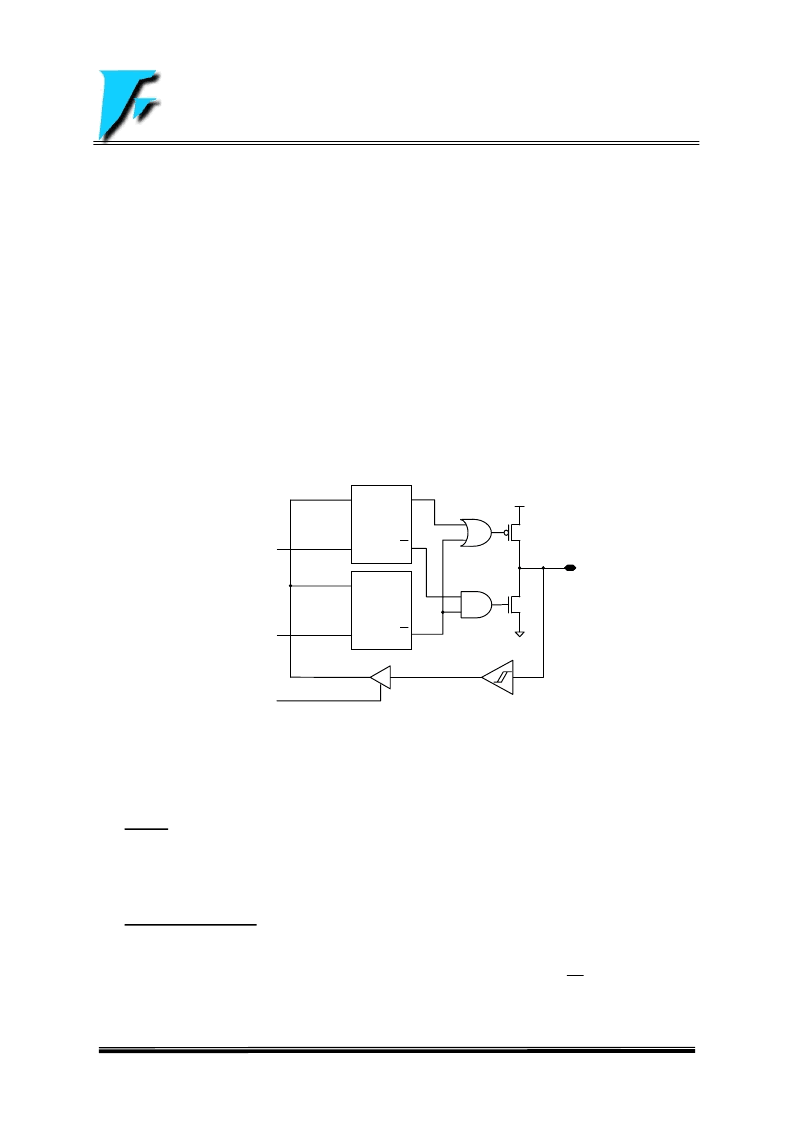
2.2 I/O Ports
Port A, port B, port C, port D and port E are bi-directional tri-state I/O ports.
All I/O pins (IOA, IOB, IOC, IOD and IOE) have data direction control registers (IOSTA, IOSTB, IOSTC, IOSTD, and
IOSTE) which can configure these pins as output or input.
IOA<7:0>, IOB<7:0>, IOC<5:4>, IOD<7:0> and IOE<5:0> have corresponding pull-high control bits (/PHBCE, /PHA,
/PHB, /PHD, and /PHE bits) to enable the weak internal pull-high. The weak pull-high is automatically turned off
when the pin is configured as an output pin.
IOC6 and IOC7 have an open-drain control bit (ODE, PCON<6>) to enable the open-drain output when these pins
are configured to be an output pin.
IOD0 and IOD1 are the R-option pins enabled by setting the ROC bit (PCON<3>). When the R-option function is
used, it is recommended that IOD0 and IOD1 are used as output pins, and read the status of IOD0 and IOD1 before
these pins are configured to be an output pin.
IOB0~IOB7, IOC4~IOC5, and IOE0~IOE1 also provide the input change interrupt/wake-up function which are
enabled by clear /WUE bit (PCON<0>). The input change interrupt/wake-up function is automatically turned off
when the pin is configured as an output pin.
FIGURE 2.3: Block Diagram of I/O PINs
Pull-high/R-option is not shown in the figure
2.3 Timer0/WDT & Prescler
2.3.1
Timer0
The Timer0 is a 8-bit timer/counter. The clock source of Timer0 comes from the internal clock.
The timer0 register (TMR0) will increment every instruction cycle (without prescaler). If TMR0 register is written, the
increment is inhibited for the following two cycles.
2.3.2 Watchdog Timer (WDT)
The Watchdog Timer (WDT) is a free running on-chip RC oscillator which does not require any external components.
So the WDT will still run even if the clock on the OSCI and OSCO pins is turned off, such as in SLEEP mode. During
normal operation or in SLEEP mode, a WDT time-out will cause the device reset and the TO bit (STATUS<4>) will
be cleared.
The WDT can be disabled by clearing the control bit WDTE (PCON<5>) to “0”.
The WDT has a nominal time-out period of 18 ms (without prescaler). If a longer time-out period is desired, a
D Q
IOST
Latch
> EN
Q
I/O PIN
D Q
DATA
Latch
> EN Q
Data bus
IOST R
WR PORT
RD PORT
相關(guān)PDF資料 |
PDF描述 |
|---|---|
| FM8P51EP | EPROM/ROM-Based 8-Bit Microcontroller |
| FM8P51F | EPROM/ROM-Based 8-Bit Microcontroller |
| FM8P51P | EPROM/ROM-Based 8-Bit Microcontroller |
| FM8P51E | EPROM/ROM-Based 8-Bit Microcontroller |
| FM8P54 | EPROM/ROM-Based 8-Bit Microcontroller Series |
相關(guān)代理商/技術(shù)參數(shù) |
參數(shù)描述 |
|---|---|
| FM8P51EP | 制造商:未知廠家 制造商全稱:未知廠家 功能描述:EPROM/ROM-Based 8-Bit Microcontroller |
| FM8P51F | 制造商:未知廠家 制造商全稱:未知廠家 功能描述:EPROM/ROM-Based 8-Bit Microcontroller |
| FM8P51P | 制造商:未知廠家 制造商全稱:未知廠家 功能描述:EPROM/ROM-Based 8-Bit Microcontroller |
| FM8P54 | 制造商:未知廠家 制造商全稱:未知廠家 功能描述:EPROM/ROM-Based 8-Bit Microcontroller Series |
| FM8P54E | 制造商:未知廠家 制造商全稱:未知廠家 功能描述:EPROM/ROM-Based 8-Bit Microcontroller Series |
發(fā)布緊急采購,3分鐘左右您將得到回復(fù)。