- 您現(xiàn)在的位置:買賣IC網(wǎng) > PDF目錄375269 > ADV7195 (Analog Devices, Inc.) Multiformat Progressive Scan/HDTV Encoder with Three 11-Bit DACs and 10-Bit Data Input PDF資料下載
參數(shù)資料
| 型號(hào): | ADV7195 |
| 廠商: | Analog Devices, Inc. |
| 英文描述: | Multiformat Progressive Scan/HDTV Encoder with Three 11-Bit DACs and 10-Bit Data Input |
| 中文描述: | 多格式逐行掃描/高清晰度電視編碼器三種11位DAC和10位數(shù)據(jù)輸入 |
| 文件頁(yè)數(shù): | 23/36頁(yè) |
| 文件大小: | 499K |
| 代理商: | ADV7195 |
第1頁(yè)第2頁(yè)第3頁(yè)第4頁(yè)第5頁(yè)第6頁(yè)第7頁(yè)第8頁(yè)第9頁(yè)第10頁(yè)第11頁(yè)第12頁(yè)第13頁(yè)第14頁(yè)第15頁(yè)第16頁(yè)第17頁(yè)第18頁(yè)第19頁(yè)第20頁(yè)第21頁(yè)第22頁(yè)當(dāng)前第23頁(yè)第24頁(yè)第25頁(yè)第26頁(yè)第27頁(yè)第28頁(yè)第29頁(yè)第30頁(yè)第31頁(yè)第32頁(yè)第33頁(yè)第34頁(yè)第35頁(yè)第36頁(yè)
REV. 0
ADV7195
–23–
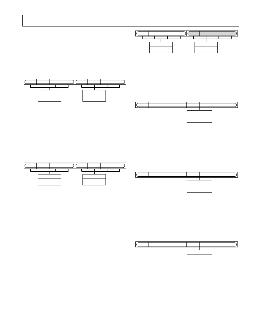
ADAPTIVE FILTER GAIN 1
AFG1 (AFG1)7–0
(Address (SR5-SR0) = 22H)
This 8-bit-wide register is used to program the gain applied to
signals which lie above Adaptive Filter Threshold A but are
smaller than Adaptive Filter Threshold B.
Gain A and Gain B values vary from –8 to +7.
Settings for (AFG1)3–0 have no effect unless Adaptive Mode
Control is set to Mode B (MR56 = “1”).
GAIN B
AFG17
–
AFG14
AFG17
AFG16
AFG15
AFG14
AFG13
AFG12
AFG11
AFG10
GAIN A
AFG13
–
AFG10
Figure 38. Adaptive Filter Gain 1 Register
ADAPTIVE FILTER GAIN 2
AFG2 (AFG2)7–0
(Address (SR5–SR0) = 23H)
This 8-bit-wide register is used to program the gain applied to
signals which lie above Adaptive Filter Threshold B but are
smaller than Adaptive Filter Threshold C.
Gain A and Gain B values vary from –8 to +7.
Settings for (AFG2)3–0 have no effect unless Adaptive Mode
Control is set to Mode B (MR56 = “1”).
GAIN B
AFG27
–
AFG24
AFG27
AFG26
AFG25
AFG24
AFG23
AFG22
AFG21
AFG20
GAIN A
AFG23
–
AFG20
Figure 39. Adaptive Filter Gain 2 Register
ADAPTIVE FILTER GAIN 3
AFG3 (AFG3)7–0
(Address (SR5–SR0) = 24H)
This 8-bit-wide register is used to program the gain applied to
signals that lie above Adaptive Filter Threshold C.
Gain A and Gain B values vary from –8 to +7.
Settings for (AFG3)3–0 have no effect unless Adaptive Mode
Control is set to Mode B (MR56 = “1”).
The gain applied to signals that lie below Adaptive Threshold A
is programmed in the Filter Gain register.
At any one time only one of the following registers is active:
AFG1, AFG2, AFG3, FG. The gain values can be prepro-
grammed and become active whenever the threshold conditions
for the according register are met. To program the Adaptive
Filter Gain registers the same register settings are used as for the
Filter Gain register.
GAIN B
AFG37
–
AFG34
AFG37
AFG36
AFG35
AFG34
AFG33
AFG32
AFG31
AFG30
GAIN A
AFG33
–
AFG30
Figure 40. Adaptive Filter Gain 3 Register
ADAPTIVE FILTER THRESHOLD A
AFTA AFTA7–0
(Address (SR5–SR0) = 25H)
This 8-bit-wide register is used to program the threshold value
for small edges. The recommended programmable threshold
range is from 16–235, although any value in the range of 0–255
can be used.
ADAPTIVE FILTER
THRESHOLD A
AFTA7
–
AFTA0
AFTA7
AFTA6
AFTA5
AFTA4
AFTA3
AFTA2
AFTA1
AFTA0
Figure 41. Adaptive Filter Threshold A Register
ADAPTIVE FILTER THRESHOLD B
AFTB AFTB7–0
(Address (SR5–SR0) = 26H)
This 8-bit-wide register is used to program the threshold value
for medium edges and has priority over Adaptive Threshold A.
The recommended programmable threshold range is from
16–235, although any value in the range of 0–255 can be used.
ADAPTIVE FILTER
THRESHOLD B
AFTB7
–
AFTB0
AFTB7
AFTB6
AFTB5
AFTB4
AFTB3
AFTB2
AFTB1
AFTB0
Figure 42. Adaptive Filter Threshold B Register
ADAPTIVE FILTER THRESHOLD C
AFTC AFTC7–0
(Address (SR5–SR0) = 27H)
This 8-bit-wide register is used to program the threshold value
for large edges and has priority over Adaptive Threshold A and
B. The recommended programmable threshold range is from
16–235, although any value in the range of 0–255 can be used.
ADAPTIVE FILTER
THRESHOLD C
AFTC7
–
AFTC0
AFTC7
AFTC6
AFTC5
AFTC4
AFTC3
AFTC2
AFTC1
AFTC0
Figure 43. Adaptive Filter Threshold C
相關(guān)PDF資料 |
PDF描述 |
|---|---|
| ADV7195KST | Multiformat Progressive Scan/HDTV Encoder with Three 11-Bit DACs and 10-Bit Data Input |
| ADV7196 | Multiformat Progressive Scan/HDTV Encoder with Three 11-Bit DACs, 10-Bit Data Input, and Macrovision |
| ADV7196A | Multiformat Progressive Scan/HDTV Encoder with Three 11-Bit DACs, 10-Bit Data Input, and Macrovision |
| ADV7196AKS | Multiformat Progressive Scan/HDTV Encoder with Three 11-Bit DACs, 10-Bit Data Input, and Macrovision |
| ADV7197 | Multiformat HDTV Encoder with Three 11-Bit DACs |
相關(guān)代理商/技術(shù)參數(shù) |
參數(shù)描述 |
|---|---|
| ADV7195KS | 制造商:Analog Devices 功能描述:Video Encoder 3DAC 11-Bit 52-Pin MQFP 制造商:Rochester Electronics LLC 功能描述:MULTI-FORMAT VID+PROGSCAN/HDTV ENCODERIC - Bulk |
| ADV7195KST | 制造商:AD 制造商全稱:Analog Devices 功能描述:Multiformat Progressive Scan/HDTV Encoder with Three 11-Bit DACs and 10-Bit Data Input |
| ADV7195KSZ | 制造商:Analog Devices 功能描述:Video Encoder 3DAC 11-Bit 52-Pin MQFP |
| ADV7196 | 制造商:AD 制造商全稱:Analog Devices 功能描述:Multiformat Progressive Scan/HDTV Encoder with Three 11-Bit DACs, 10-Bit Data Input, and Macrovision |
| ADV7196A | 制造商:AD 制造商全稱:Analog Devices 功能描述:Multiformat Progressive Scan/HDTV Encoder with Three 11-Bit DACs, 10-Bit Data Input, and Macrovision |
發(fā)布緊急采購(gòu),3分鐘左右您將得到回復(fù)。