- 您現(xiàn)在的位置:買賣IC網(wǎng) > PDF目錄374016 > ADM9240ARU (ANALOG DEVICES INC) Low Cost Microprocessor System Hardware Monitor PDF資料下載
參數(shù)資料
| 型號(hào): | ADM9240ARU |
| 廠商: | ANALOG DEVICES INC |
| 元件分類: | 電源管理 |
| 英文描述: | Low Cost Microprocessor System Hardware Monitor |
| 中文描述: | 9-CHANNEL POWER SUPPLY SUPPORT CKT, PDSO24 |
| 封裝: | TSSOP-24 |
| 文件頁(yè)數(shù): | 12/22頁(yè) |
| 文件大小: | 280K |
| 代理商: | ADM9240ARU |
第1頁(yè)第2頁(yè)第3頁(yè)第4頁(yè)第5頁(yè)第6頁(yè)第7頁(yè)第8頁(yè)第9頁(yè)第10頁(yè)第11頁(yè)當(dāng)前第12頁(yè)第13頁(yè)第14頁(yè)第15頁(yè)第16頁(yè)第17頁(yè)第18頁(yè)第19頁(yè)第20頁(yè)第21頁(yè)第22頁(yè)
ADM9240
–12–
REV. 0
FAN INPUT S
T wo inputs are provide for monitoring the condition of cooling
fans. Signal conditioning in the ADM9240 accommodates the
slow rise and fall times typical of fan tachometer outputs. T he
maximum input signal range is 0 to V
CC
. In the event that these
inputs are supplied from fan outputs that exceed 0 to V
CC
,
either resistive attenuation of the fan signal or diode clamping
must be included to keep inputs within an acceptable range.
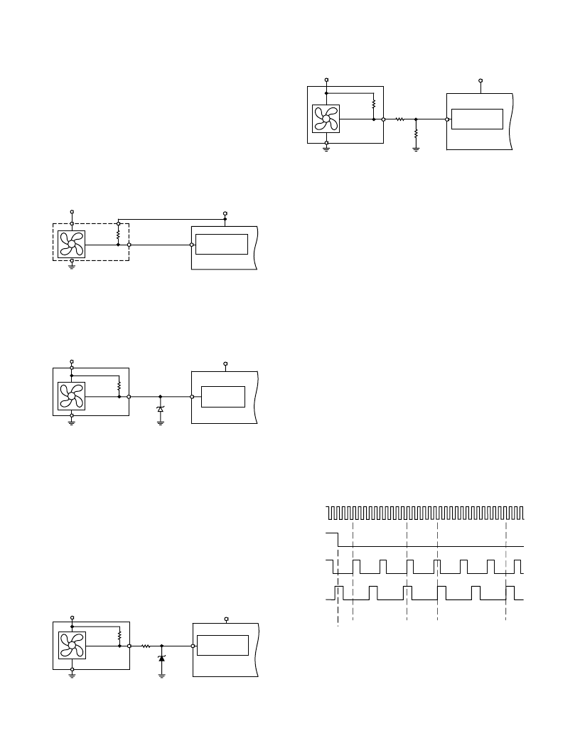
Figures 6a to 6c show circuits for most common fan tacho
outputs.
If the fan tacho output has a resistive pull-up to V
CC
it can be
connected directly to the fan input, as shown in Figure 6a.
+12V
FAN1
OR FAN2
PULL-UP
4TYP.
V
TACHO
OUTPUT
V
CC
FAN SPEED
COUNTER
Figure 6a. Fan with Tachometer Pull-Up to +V
CC
If the fan output has a resistive pull-up to +12 V (or other
voltage greater than V
CC
), the fan output can be clamped with
a Zener diode, as shown in Figure 6b. T he Zener voltage
should be chosen so that it is greater than V
IH
but less than
V
CC
, allowing for the voltage tolerance of the Zener. A value of
about 0.8
×
V
CC
is suitable.
+12V
FAN1
OR FAN2
PULL-UP
4TYP.
V
TACHO
OUTPUT
V
CC
ZD1*
ZENER
*CHOOSE ZD1 VOLTAGE APPROX. 0.8
3
V
CC
FAN SPEED
COUNTER
Figure 6b. Fan with Tachometer Pull-Up to Voltage >V
CC
(e.g., 12 V) Clamped with Zener Diode
If the fan has a strong pull-up (less than 1 k
) to +12 V, or a
totem-pole output, a series resistor can be added to limit the
zener current, as shown in Figure 6c. Alternatively, a resistive
attenuator may be used, as shown in Figure 6d.
R1 and R2 should be chosen such that:
2
V
<
V
PULL-UP
×
R
2/(
R
PULL-UP
+
R
1 +
R
2) <
V
CC
If the value of the pull-up resistor is not known, the value of
R
1
and
R
2 should be made fairly large, but not so large that the
input leakage current will cause a large voltage drop across
them.
With a pull-up voltage of 12 V and pull-up resistor less than
1 k
, suitable values for R1 and R2 would be 100 k
and
47 k
. T his will give a high input voltage of 3.83 V.
+12V
FAN1
OR FAN2
PULL-UP
TYP. < 1k
OR TOTEM-POLE
TACHO
OUTPUT
V
CC
FAN SPEED
COUNTER
ZD1*
ZENER
*CHOOSE ZD1 VOLTAGE APPROX. 0.8
3
V
CC
R1
10k
V
Figure 6c. Fan with Strong Tachometer Pull-Up to
>V
CC
or Totem-Pole Output, Clamped with Zener and
Resistor
+12V
FAN1
OR FAN2
< 1k
V
TACHO
OUTPUT
V
CC
FAN SPEED
COUNTER
*SEE TEXT
R1*
R2*
Figure 6d. Fan with Strong Tachometer Pull-Up to
>V
CC
or Totem-Pole Output, Attenuated with R1/R2
INPUT CURRE NT LIMIT ING
If the fans are powered while the ADM9240 is unpowered, the
inputs of the ADM9240 will try to clamp the fan output volt-
age. In this case the input current must be limited to less than
the maximum value in the Absolute Maximum Ratings table.
T he pull-up resistor of the fan tacho output may provide this
current limiting but, if its value is too low, it may be necessary
to add additional resistance in series with the fan input pins.
FAN SPE E D ME ASURE ME NT
T he fan counter does not count the fan tacho output pulses
directly, because the fan speed may be less than 1000 rpm and
it would take several seconds to accumulate a reasonably large
and accurate count. Instead, the period of the fan revolution is
measured by gating an on-chip 22.5 kHz oscillator into the
input of an 8-bit counter for two periods of the fan tacho out-
put, as shown in Figure 7, so the accumulated count is actually
proportional to the fan tacho period and inversely proportional
to the fan speed.
T he monitoring cycle begins when a one is written to the start
bit (Bit 0), and a zero to the
INT
_Clear bit (Bit 3) of the Con-
figuration Register
INT
_Enable (Bit 1) should be set to one to
enable the
INT
output. T he measurement begins on the rising
edge of a fan tacho pulse, and ends on the next-but-one rising
edge. Once the fan speeds have been measured, they will be
stored in the Fan Speed Value Registers and can be read at any
time. T he measurements will be updated as long as the moni-
toring cycle continues.
22.5kHz
CLOCK
CONFIG
REG. BIT 0
FAN1
INPUT
FAN1
MEASUREMENT
PERIOD
FAN2
MEASUREMENT
PERIOD
START OF
MONITORING
CYCLE
FAN2
INPUT
Figure 7. Fan Speed Measurement
相關(guān)PDF資料 |
PDF描述 |
|---|---|
| ADM9261 | Triple- Power Supply Monitor(3路電源監(jiān)視器) |
| ADM9264ARN-REEL | Quad Power Supply Monitor for Desktop PCs |
| ADM9264ARN-REEL7 | Quad Power Supply Monitor for Desktop PCs |
| ADM9264 | Quad Power Supply Monitor for Desktop PCs |
| ADM9264ARN | Quad Power Supply Monitor for Desktop PCs |
相關(guān)代理商/技術(shù)參數(shù) |
參數(shù)描述 |
|---|---|
| ADM9240ARU-REEL | 制造商:AD 制造商全稱:Analog Devices 功能描述:Low Cost Microprocessor System Hardware Monitor |
| ADM9240ARU-REEL7 | 制造商:Analog Devices 功能描述: |
| ADM9264 | 制造商:AD 制造商全稱:Analog Devices 功能描述:Quad Power Supply Monitor for Desktop PCs |
| ADM9264ARN | 制造商:Analog Devices 功能描述:Volt Supervisor Monitor 2.8V/3.3V/5V/12V 16-Pin SOIC N 制造商:Rochester Electronics LLC 功能描述:MULTI-SUPPLY HARDWARE MON - Bulk |
| ADM9264ARN-REEL | 制造商:Rochester Electronics LLC 功能描述:- Tape and Reel |
發(fā)布緊急采購(gòu),3分鐘左右您將得到回復(fù)。