- 您現(xiàn)在的位置:買賣IC網(wǎng) > PDF目錄165348 > ADE7757AARZ (ANALOG DEVICES INC) SPECIALTY ANALOG CIRCUIT, PDSO16 PDF資料下載
參數(shù)資料
| 型號(hào): | ADE7757AARZ |
| 廠商: | ANALOG DEVICES INC |
| 元件分類: | 模擬信號(hào)調(diào)理 |
| 英文描述: | SPECIALTY ANALOG CIRCUIT, PDSO16 |
| 封裝: | LEAD FREE, MS-012AC, SOIC-16 |
| 文件頁數(shù): | 2/24頁 |
| 文件大小: | 391K |
| 代理商: | ADE7757AARZ |
ADE7757A
Preliminary Technical Data
Rev. PrE | Page 10 of 24
THEORY OF OPERATION
The two ADCs in the ADE7757A digitize the voltage signals
from the current and voltage sensors. These ADCs are 16-bit
Σ-Δ with an oversampling rate of 450 kHz. This analog input
structure greatly simplifies sensor interfacing by providing a
wide dynamic range for direct connection to the sensor and also
simplifies the antialiasing filter design. A high-pass filter in the
current channel removes any dc component from the current
signal. This eliminates any inaccuracies in the real power
calculation due to offsets in the voltage or current signals.
Because the HPF is always enabled, the IC operates only with ac
input (see the HPF and Offset Effects section).
The real power calculation is derived from the instantaneous
power signal. The instantaneous power signal is generated by
a direct multiplication of the current and voltage signals. In
order to extract the real power component (that is, the dc
component), the instantaneous power signal is low-pass filtered.
Figure 15 illustrates the instantaneous real power signal and
shows how the real power information can be extracted by low-
pass filtering the instantaneous power signal. This scheme
correctly calculates real power for sinusoidal current and
voltage waveforms at all power factors. All signal processing is
carried out in the digital domain for superior stability over
temperature and time.
TIME
ADC
CH1
CH2
MULTIPLIER
F1
F2
DIGITAL-TO-
FREQUENCY
CF
DIGITAL-TO-
FREQUENCY
INSTANTANEOUS REAL
POWER SIGNAL
INSTANTANEOUS
POWER SIGNAL – p(t)
LPF
HPF
05330-005
Figure 15. Signal Processing Block Diagram
The low frequency outputs (F1, F2) of the ADE7757A are
generated by accumulating this real power information. This
low frequency inherently means a long accumulation time
between output pulses. Consequently, the resulting output
frequency is proportional to the average real power. This
average real power information is then accumulated (for
example, by a counter) to generate real energy information.
Conversely, due to its high output frequency and hence shorter
integration time, the CF output frequency is proportional to the
instantaneous real power. This is useful for system calibration,
which can be done faster under steady load conditions.
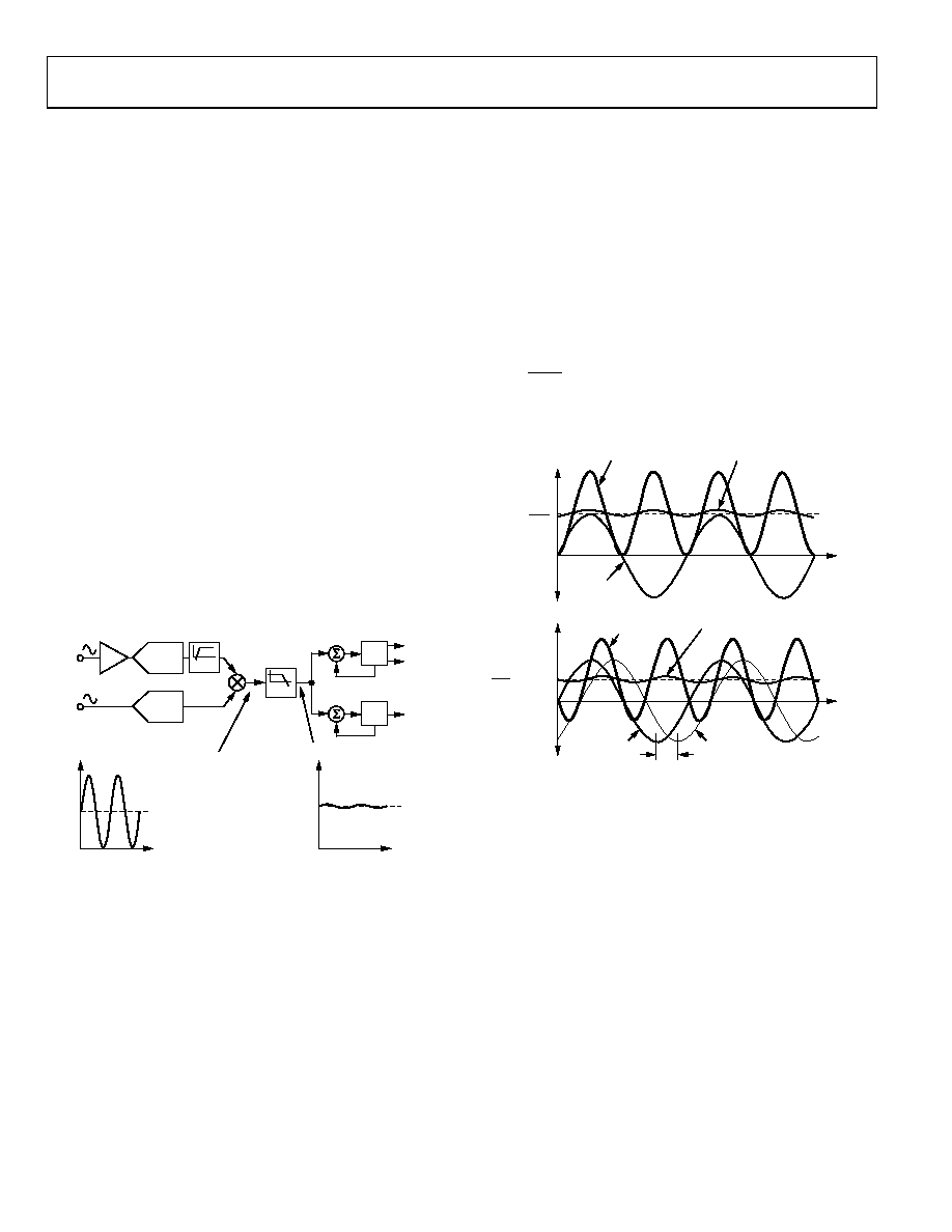
POWER FACTOR CONSIDERATIONS
The method used to extract the real power information from
the instantaneous power signal (that is, by low-pass filtering) is
still valid even when the voltage and current signals are not in
phase. Figure 16 displays the unity power factor condition and
a displacement power factor (DPF) = 0.5—that is, the current
signal lagging the voltage by 60. Assuming the voltage and
current waveforms are sinusoidal, the real power component of
the instantaneous power signal (the dc term) is given by
()°
×
×
60
cos
2
I
V
(1)
This is the correct real power calculation.
V
× I
2
0V
POWER
CURRENT
VOLTAGE
POWER
TIME
VOLTAGE
CURRENT
V
× I
2
COS (60
°)
0V
INSTANTANEOUS
POWER SIGNAL
INSTANTANEOUS REAL
POWER SIGNAL
INSTANTANEOUS
POWER SIGNAL
INSTANTANEOUS REAL
POWER SIGNAL
60
°
05330-006
Figure 16. DC Component of Instantaneous Power Signal Conveys Real
Power Information, PF < 1
相關(guān)PDF資料 |
PDF描述 |
|---|---|
| ADF02S | SLIDE DIP SWITCH-2SWITCHES, SPST, LATCHED,SURFACE MOUNT-STRAIGHT |
| ADF4213BCPZ-REEL7 | PLL FREQUENCY SYNTHESIZER, 3000 MHz, QCC20 |
| ADF4212BRUZ-REEL7 | PLL FREQUENCY SYNTHESIZER, 2700 MHz, PDSO20 |
| ADG1409SRU-EP-RL7 | 4-CHANNEL, DIFFERENTIAL MULTIPLEXER, PDSO16 |
| ADG726BCP-REEL7 | 16-CHANNEL, DIFFERENTIAL MULTIPLEXER, QCC48 |
相關(guān)代理商/技術(shù)參數(shù) |
參數(shù)描述 |
|---|---|
| ADE7757ARN | 制造商:Rochester Electronics LLC 功能描述:ENERGY METER IC W/INTEGRATED OSCILLATOR - Bulk 制造商:Analog Devices 功能描述:IC ENERGY METER |
| ADE7757ARN-REF | 制造商:Analog Devices 功能描述:REF BOARD ENERGY MTR W/INTGRATED OSCIL. - Rail/Tube |
| ADE7757ARNRL | 制造商:Analog Devices 功能描述:IC ENERGY METERING 16-SOIC TR |
| ADE7757ARNZ | 功能描述:IC ENERGY METERING 1PHASE 16SOIC RoHS:是 類別:集成電路 (IC) >> PMIC - 能量測(cè)量 系列:- 產(chǎn)品培訓(xùn)模塊:Lead (SnPb) Finish for COTS Obsolescence Mitigation Program 標(biāo)準(zhǔn)包裝:2,500 系列:* |
| ADE7757ARNZRL | 功能描述:IC ENERGY METERING 1PHASE 16SOIC RoHS:是 類別:集成電路 (IC) >> PMIC - 能量測(cè)量 系列:- 產(chǎn)品培訓(xùn)模塊:Lead (SnPb) Finish for COTS Obsolescence Mitigation Program 標(biāo)準(zhǔn)包裝:2,500 系列:* |
發(fā)布緊急采購,3分鐘左右您將得到回復(fù)。