- 您現(xiàn)在的位置:買賣IC網(wǎng) > PDF目錄36339 > 935264530157 (NXP SEMICONDUCTORS) SPECIALTY CONSUMER CIRCUIT, PQFP100 PDF資料下載
參數(shù)資料
| 型號: | 935264530157 |
| 廠商: | NXP SEMICONDUCTORS |
| 元件分類: | 消費家電 |
| 英文描述: | SPECIALTY CONSUMER CIRCUIT, PQFP100 |
| 封裝: | SOT-317, MQFP-100 |
| 文件頁數(shù): | 26/43頁 |
| 文件大?。?/td> | 254K |
| 代理商: | 935264530157 |
第1頁第2頁第3頁第4頁第5頁第6頁第7頁第8頁第9頁第10頁第11頁第12頁第13頁第14頁第15頁第16頁第17頁第18頁第19頁第20頁第21頁第22頁第23頁第24頁第25頁當(dāng)前第26頁第27頁第28頁第29頁第30頁第31頁第32頁第33頁第34頁第35頁第36頁第37頁第38頁第39頁第40頁第41頁第42頁第43頁
1999 March 01
32
Philips Semiconductors
Product specication
Single chip DVB-C channel receiver
VES1820X
BOUNDARY SCAN
VES1820X implements a boundary scan architecture to allow access to, and control of, board test support features
within integrated circuits through a Test Access Port (TAP). The TAP controller is a synchronous state machine that
controls the sequence operations on the TAP circuitry when the Test Mode Select (TMS) signal changes. All state
transitions occur on the basis of the TMS value on the rising edge of Test ClocK (TCK). The instruction register is a
shift-register based design. It decodes the test to be performed and/or the test data register to be accessed. The
instructions are shifted into the register through the Test Data Input (TDI) and are latched as the current instruction
at the completion of the shifting process. The VES1820X implemented boundary scan architecture includes : a TAP
controller, a scannable instruction register and three scannable test data registers : a boundary scan register, a
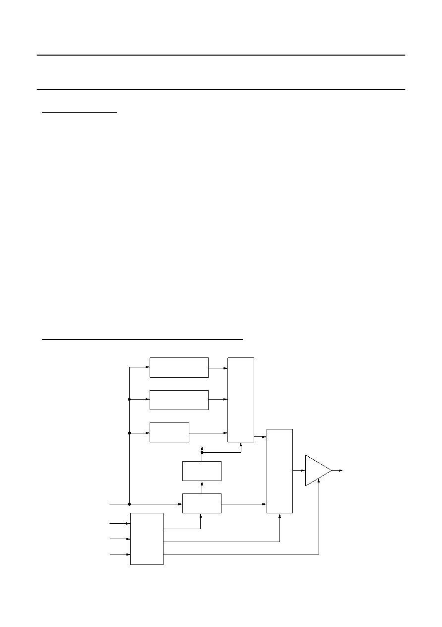
device ID register, and a bypass register (see FIGURE 14 page 32 ).
The supported instructions are : EXTEST, SAMPLE, IDCODE, and BYPASS.
CELLS : Input cells are "observe-only" type and output cells are "observe and control" type.
ID number : It is included in a 32-bit identification register which is included in the scan register itself (first 32-bit of
scan register). It contains a fixed value which identifies the chip.
ID number structure is :
ID version :
’H1
ID part number :
’H1820
ID manufacturer :
’HAB
IDCODE :
’H11820157
SCAN Register : It is composed of 61 cells. Each cell is associated either to an input, three-state output,
bidirectional pad or to the bidirectional or three-state command itself.
FIGURE 14 : BOUNDARY SCAN BLOCK DIAGRAM
TDI
TCK
TRST
TMS
TDO
BOUNDARY SCAN
REGISTER
DEVICE ID REGISTER
BYPASS
REGISTER
CONTROL
INSTRUCTION
MUX FF
SELECT
3-STATE ENABLE
TEST
ACCESS
PORT
CONTROLLER
INSTRUCTION
DECODE
REGISTER
MUX.
相關(guān)PDF資料 |
PDF描述 |
|---|---|
| 935264533557 | SPECIALTY CONSUMER CIRCUIT, PQFP100 |
| 935264539557 | SPECIALTY CONSUMER CIRCUIT, PQFP100 |
| 935266871557 | SPECIALTY CONSUMER CIRCUIT, PBGA292 |
| 935266917557 | SPECIALTY CONSUMER CIRCUIT, PBGA292 |
| 935268386557 | SPECIALTY CONSUMER CIRCUIT, PBGA292 |
相關(guān)代理商/技術(shù)參數(shù) |
參數(shù)描述 |
|---|---|
| 935267356112 | 制造商:NXP Semiconductors 功能描述:IC TEA1507PN |
| 935268081112 | 制造商:NXP Semiconductors 功能描述:SUB ONLY IC |
| 935268721125 | 制造商:NXP Semiconductors 功能描述:Buffer/Line Driver 1-CH Non-Inverting 3-ST CMOS 5-Pin TSSOP T/R |
| 935269304128 | 制造商:ST-Ericsson 功能描述:IC AUDIO CODEC W/TCH SCRN 48LQFP |
| 935269544557 | 制造商:NXP Semiconductors 功能描述:SUB ONLY TDA9587-2US1-V1.3 |
發(fā)布緊急采購,3分鐘左右您將得到回復(fù)。