- 您現(xiàn)在的位置:買賣IC網(wǎng) > PDF目錄359786 > VV5410C036 (意法半導(dǎo)體) Mono and Colour Digital Video CMOS Image Sensors PDF資料下載
參數(shù)資料
| 型號: | VV5410C036 |
| 廠商: | 意法半導(dǎo)體 |
| 英文描述: | Mono and Colour Digital Video CMOS Image Sensors |
| 中文描述: | 莫諾和數(shù)字視頻彩色CMOS圖像傳感器 |
| 文件頁數(shù): | 61/105頁 |
| 文件大?。?/td> | 489K |
| 代理商: | VV5410C036 |
第1頁第2頁第3頁第4頁第5頁第6頁第7頁第8頁第9頁第10頁第11頁第12頁第13頁第14頁第15頁第16頁第17頁第18頁第19頁第20頁第21頁第22頁第23頁第24頁第25頁第26頁第27頁第28頁第29頁第30頁第31頁第32頁第33頁第34頁第35頁第36頁第37頁第38頁第39頁第40頁第41頁第42頁第43頁第44頁第45頁第46頁第47頁第48頁第49頁第50頁第51頁第52頁第53頁第54頁第55頁第56頁第57頁第58頁第59頁第60頁當(dāng)前第61頁第62頁第63頁第64頁第65頁第66頁第67頁第68頁第69頁第70頁第71頁第72頁第73頁第74頁第75頁第76頁第77頁第78頁第79頁第80頁第81頁第82頁第83頁第84頁第85頁第86頁第87頁第88頁第89頁第90頁第91頁第92頁第93頁第94頁第95頁第96頁第97頁第98頁第99頁第100頁第101頁第102頁第103頁第104頁第105頁
CMOS Sensor; Customer Datasheet, Rev 3.0, 28 September 2000
VV5410 & VV6410
Commercial in confidence
cd5410-6410f-3-0.fm
The byte following the address byte contains the address of the first data byte (also referred to as the index). The serial interface
can address up to 128, byte registers. If the msb of the second byte is set the automatic increment feature of the address index is
selected.
9.4
All serial interface communications with the sensor must begin with a startcondition. If the start condition is followed by a valid
address byte then further communications can take place. The sensor will acknowledge the receipt of a valid address by driving
the sda wire low. The state of the read/~writebit (lsb of the address byte) is stored and the next byte of data, sampled from
can be interpreted.
Message Interpretation
During a write sequence the second byte received is an address index and is used to point to one of the internal registers. The
msbit of the following byte is the index auto incrementflag. If this flag is set then the serial interface will automatically increment
the index address by one location after each slave acknowledge. The master can therefore send data bytes continuously to the
slave until the slave fails to provide an acknowledge or the master terminates the write communication with a
sends a repeated start (Sr) If the auto increment feature is used the master does nothave to send indexes to accompany the
data bytes.
condition or
As data is received by the slave it is written bit by bit to a serial/parallel register. After each data byte has been received by the
slave, an acknowledge is generated, the data is then stored in the internal register addressed by the current index.
During a read message, the current index is read out in the byte following the device address byte. The next byte read from the
slave device are the contents of the register addressed by the current index. The contents of this register are then parallel loaded
into the serial/parallel register and clocked out of the device by scl.
At the end of each byte, in both read and write message sequences, an acknowledge is issued by the receiving device. Although
VV5410/VV6410 is always considered to be a slave device, it acts as a transmitter when the bus master requests a read from the
sensor.
At the end of a sequence of incremental reads or writes, the terminal index value in the register will be one greaterthe last
location read from or written to. A subsequent read will use this index to begin retrieving data from the internal registers.
A message can only be terminated by the bus master, either by issuing a stop condition, a repeated start condition or by a
negative acknowledge after reading a complete byte during a read operation.
9.5
There may be up to 128, 8-bit registers within the camera, accessible by the user via the serial interface. They are grouped
The Programmers Model
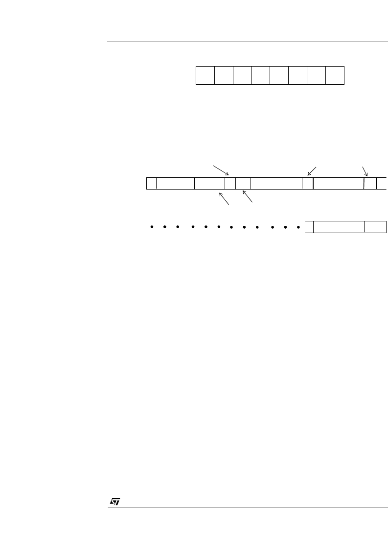
0
0
1
0
0
0
0
Figure 36 : VV5410/VV6410’s Serial Interface Address
R/W
S
address[7:1]
R
/
W
bit
A
DATA[7:0]
A
Sensor acknowledges valid address
Acknowledge from slave
INDEX[6:0]
INC
P
A
A
DATA[7:0]
[0]
address
Auto increment
Index bit
Figure 37 : Serial Interface Data Format
相關(guān)PDF資料 |
PDF描述 |
|---|---|
| V912I | Rail-to-rail input/output 8MHz operational amplifiers |
| V912IY | Rail-to-rail input/output 8MHz operational amplifiers |
| V914AI | Rail-to-rail input/output 8MHz operational amplifiers |
| V914AY | Rail-to-rail input/output 8MHz operational amplifiers |
| V914I | Rail-to-rail input/output 8MHz operational amplifiers |
相關(guān)代理商/技術(shù)參數(shù) |
參數(shù)描述 |
|---|---|
| VV5430 | 制造商:未知廠家 制造商全稱:未知廠家 功能描述:Integrated CMOS Image Sensor with support for ADC and external control via serial interface |
| VV5430C001 | 制造商:STMICROELECTRONICS 制造商全稱:STMicroelectronics 功能描述:Monochrome Analog Output CMOS Image Sensors |
| VV5501C001 | 功能描述:視頻 IC Monochrome Sensor RoHS:否 制造商:Fairchild Semiconductor 工作電源電壓:5 V 電源電流:80 mA 最大工作溫度:+ 85 C 封裝 / 箱體:TSSOP-28 封裝:Reel |
| VV5F3-30-041 | 制造商:SMC Corporation of America 功能描述:Manifold Base for VF series, base mt, 1/4 inch |
| VV5F3-30-051 | 制造商:SMC 功能描述:1/4in Five way manifold |
發(fā)布緊急采購,3分鐘左右您將得到回復(fù)。