- 您現(xiàn)在的位置:買賣IC網(wǎng) > PDF目錄383980 > UPD16878 (NEC Corp.) MONOLITHIC QUAD H BRIDGE DRIVER CIRCUIT PDF資料下載
參數(shù)資料
| 型號(hào): | UPD16878 |
| 廠商: | NEC Corp. |
| 英文描述: | MONOLITHIC QUAD H BRIDGE DRIVER CIRCUIT |
| 中文描述: | 單片四H橋驅(qū)動(dòng)電路 |
| 文件頁(yè)數(shù): | 17/32頁(yè) |
| 文件大小: | 242K |
| 代理商: | UPD16878 |
第1頁(yè)第2頁(yè)第3頁(yè)第4頁(yè)第5頁(yè)第6頁(yè)第7頁(yè)第8頁(yè)第9頁(yè)第10頁(yè)第11頁(yè)第12頁(yè)第13頁(yè)第14頁(yè)第15頁(yè)第16頁(yè)當(dāng)前第17頁(yè)第18頁(yè)第19頁(yè)第20頁(yè)第21頁(yè)第22頁(yè)第23頁(yè)第24頁(yè)第25頁(yè)第26頁(yè)第27頁(yè)第28頁(yè)第29頁(yè)第30頁(yè)第31頁(yè)第32頁(yè)
Data Sheet S15974EJ1V0DS
17
μ
PD16878
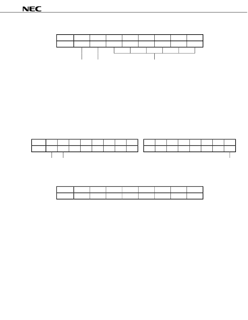
Table 5-8. 2nd Byte Data Configuration (Standard data)
Bit
D7
D6
D5
D4
D3
D2
D1
D0
Data
0 or 1
0 or 1
0 or 1
0 or 1
0 or 1
0 or 1
0 or 1
0 or 1
Rotation direction ENABLE Number of pulses
<3rd and 4th bytes>
The 3rd and 4th bytes select the pulse cycle of the
α
channel and which of the two reference voltages, created in
the initial mode, is to be used (CURRENT SET
α
).
The pulse cycle is specified using 15 bits : bits D0 (least significant bit) to D7 of the 3rd byte, and bits D0 to D6
(most significant bit) of the 4th byte. The pulse cycle can be set to a value in the range of 0.25 to 8191.75
μ
s in units
of 0.25
μ
s (with a 4-MHz clock).
CURRENT SET
α
is specified by bit D7 of the 4th byte. When this bit is
“
0
”
, reference voltage 1 (EVR
α
1
) is
selected; when it is
“
1
”
, reference voltage 2 (EVR
α
2
) is selected. For further information, refer to the description of the
6th byte of the initial data.
Table 5-9. 4th Byte Data Configuration (Standard data)
Table 5-10. 3rd Byte Data Configuration (Standard data)
Bit
D7
D6
D5
D4
D3
D2
D1
D0
D7
D6
D5
D4
D3
D2
D1
D0
Data
0 or 1
0 or 1
0 or 1
0 or 1
0 or 1
0 or 1
0 or 1
0 or 1
0 or 1
0 or 1
0 or 1
0 or 1
0 or 1
0 or 1
0 or 1
0 or 1
CURRENT SET
α
Most significant
bit
Least significant bit
(Reference) 6th Byte Data Configuration for Initial Data
Bit
D7
D6
D5
D4
D3
D2
D1
D0
Data
0 or 1
0 or 1
0 or 1
0 or 1
0 or 1
0 or 1
0 or 1
0 or 1
Remark
Bits D4 to D7 : Reference voltage 2 (EVR
α
2
)
Bits D0 to D3 : Reference voltage 1 (EVR
α
1
)
<5th byte>
The 5th byte specifies the rotation direction of the
β
channel, enables output of the
β
channel, and the number of
pulses (126 pulses MAX.) during the 1V
D
period (in one cycle of FF2) of the
β
channel.
Bit D7 is used to specify the rotation direction. The rotation is in the forward direction (CW mode) when this bit is
“
0
”
; it is in the reverse direction (CCW mode) when the bit is
“
1
”
.
Bit D6 is used to enable the output of the
β
channel. The
β
channel goes into a high impedance state when this bit
is
“
0
”
; it is in the conduction mode when the bit is
“
1
”
.
The number of pulses is set by bits D0 to D5. It is set by six bits in terms of software. However, the actual circuit
uses an 8-bit decoder with the low-order two bits fixed to
“
0
”
. Therefore, the number of pulses that is actually
generated during start up wait time + start up drive wait (FF2) cycle is the number of pulses input x
2. The number of
pulses can be set in a range of 0 to 126 and in units of 2 pulses.
相關(guān)PDF資料 |
PDF描述 |
|---|---|
| UPD16879GS-BGG | MONOLITHIC QUAD H BRIDGE DRIVER CIRCUIT |
| UPD16879 | MONOLITHIC QUAD H BRIDGE DRIVER CIRCUIT |
| UPD1703C-011 | PHASE LOCKED LOOP FREQUENCY SYNTHESIZER FM/AM DIGITAL TUNING SYSTEM CONTROLLER CMOS LSI |
| UPD1703C-013 | PHASE LOCKED LOOP FREQUENCY SYNTHESIZER FM/AM DIGITAL TUNING SYSTEM CONTROLLER CMOS LSI |
| UPD1703C-014 | PLL FREQUENCY SYMTHESIZER AND CONTROLLER FOR FM AND AM TUNER |
相關(guān)代理商/技術(shù)參數(shù) |
參數(shù)描述 |
|---|---|
| UPD16878GS-BGG | 制造商:NEC 制造商全稱:NEC 功能描述:MONOLITHIC QUAD H BRIDGE DRIVER CIRCUIT |
| UPD16879 | 制造商:NEC 制造商全稱:NEC 功能描述:MONOLITHIC QUAD H BRIDGE DRIVER CIRCUIT |
| UPD16879GS-BGG | 制造商:NEC 制造商全稱:NEC 功能描述:MONOLITHIC QUAD H BRIDGE DRIVER CIRCUIT |
| UPD16882 | 制造商:NEC 制造商全稱:NEC 功能描述:MONOLITHIC CD-ROM/DVD-ROM 3-PHASE SPINDLE MOTOR DRIVER |
| UPD16882GS | 制造商:NEC 制造商全稱:NEC 功能描述:MONOLITHIC CD-ROM/DVD-ROM 3-PHASE SPINDLE MOTOR DRIVER |
發(fā)布緊急采購(gòu),3分鐘左右您將得到回復(fù)。