- 您現(xiàn)在的位置:買賣IC網(wǎng) > PDF目錄200634 > UPC29S78 Useage of Three-Terminal Regulators | User's Manual[05/2000] PDF資料下載
參數(shù)資料
| 型號: | UPC29S78 |
| 英文描述: | Useage of Three-Terminal Regulators | User's Manual[05/2000] |
| 中文描述: | 使用三端穩(wěn)壓器|用戶手冊[05/2000] |
| 文件頁數(shù): | 15/35頁 |
| 文件大小: | 187K |
| 代理商: | UPC29S78 |
第1頁第2頁第3頁第4頁第5頁第6頁第7頁第8頁第9頁第10頁第11頁第12頁第13頁第14頁當(dāng)前第15頁第16頁第17頁第18頁第19頁第20頁第21頁第22頁第23頁第24頁第25頁第26頁第27頁第28頁第29頁第30頁第31頁第32頁第33頁第34頁第35頁
User’s Manual G12702EJ8V0UM00
22
5. PRECAUTIONS ON APPLICATION
Do not use a three-terminal regulator under temperature conditions or voltage conditions that exceed the ratings.
Other precautions that are specific to three-terminal regulators are shown below.
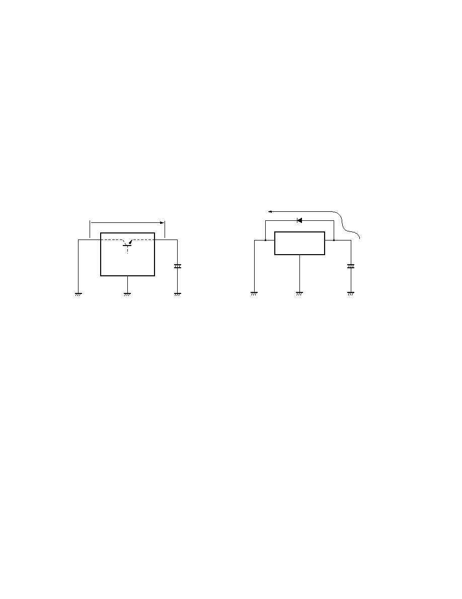
5.1 Shorting Input Pins and Ground Pins
When a capacitor with a large capacity is connected to the load of a three-terminal regulator, if the input pin is
shorted to GND or the power supply is turned OFF, the voltage of the capacitor connected to the output pin is applied
between the output and input pins of the three-terminal regulator.
Figure 5-1
(a)
(b)
VOUT
OUT
IN
GND
+
Discharge current
OUT
IN
GND
+
The withstand voltage between the output and input pins of a three-terminal regulator is approximately 0.7 V for a
low current with the output transistor base-emitter voltage.
Therefore, a diode like the one in Figure 5-1 (b) is effective against the reverse bias of the input and output pins.
Figure 5-1 (b) is for a positive voltage regulator. The diode direction is reversed for negative voltage.
5.2 Floating Ground Pins
Do not make the GND pin of a three-terminal regulator floating in the operating state. If it is made floating, an
input voltage that has not been stabilized is output unchanged. This is because the output stage power transistor is
biased by an overvoltage protection Zener or current mirror transistor leakage current. Since IC internal overheat
protection and the like do not operate normally in this case, there is a possibility of destruction if the load is short-
circuited or on an overload.
Be particularly careful when using a socket.
相關(guān)PDF資料 |
PDF描述 |
|---|---|
| UPC3025 | Useage of Three-Terminal Regulators | User's Manual[05/2000] |
| UPC1663B | Analog IC |
| UPC1663C | Analog IC |
| UPC1663P | Analog IC |
| UPC1664C | Analog IC |
相關(guān)代理商/技術(shù)參數(shù) |
參數(shù)描述 |
|---|---|
| UPC29S78GR | 制造商:NEC 制造商全稱:NEC 功能描述:LOW DROPOUT VOLTAGE REGULATOR WITH ON/OFF FUNCTION |
| UPC29S78GR-E1-A | 制造商:Renesas Electronics Corporation 功能描述: |
| UPC29S78H | 制造商:NEC 制造商全稱:NEC 功能描述:LOW DROPOUT VOLTAGE REGULATOR WITH ON/OFF FUNCTION |
| UPC29S78TA | 制造商:NEC 制造商全稱:NEC 功能描述:LOW DROPOUT VOLTAGE REGULATOR WITH ON/OFF FUNCTION |
| UPC2A23P4 | 制造商: 功能描述: 制造商:undefined 功能描述: |
發(fā)布緊急采購,3分鐘左右您將得到回復(fù)。