- 您現(xiàn)在的位置:買賣IC網(wǎng) > PDF目錄384014 > TMC2302AH5C1 (FAIRCHILD SEMICONDUCTOR CORP) Image Manipulation Sequencer PDF資料下載
參數(shù)資料
| 型號: | TMC2302AH5C1 |
| 廠商: | FAIRCHILD SEMICONDUCTOR CORP |
| 元件分類: | 數(shù)字信號處理外設(shè) |
| 英文描述: | Image Manipulation Sequencer |
| 中文描述: | 16-BIT, DSP-ADDRESS SEQUENCER, PPGA120 |
| 封裝: | CAVITY-UP, PLASTIC, PGA-120 |
| 文件頁數(shù): | 3/36頁 |
| 文件大?。?/td> | 188K |
| 代理商: | TMC2302AH5C1 |
第1頁第2頁當(dāng)前第3頁第4頁第5頁第6頁第7頁第8頁第9頁第10頁第11頁第12頁第13頁第14頁第15頁第16頁第17頁第18頁第19頁第20頁第21頁第22頁第23頁第24頁第25頁第26頁第27頁第28頁第29頁第30頁第31頁第32頁第33頁第34頁第35頁第36頁
PRODUCT SPECIFICATION
TMC2302A
3
P
Functional Description
General Information
The TMC2302A is a versatile, high-performance address
generator which can control, under user direction, filtering or
remapping of two or three-dimensional images by resam-
pling them from one set of Cartesian coordinates (x, y, z)
into a new, transformed set (u, v, w). Most applications
utilize two identical devices for two-dimensional, or three
devices for three-dimensional, image processing. The host
CPU initializes the system by loading the input image buffer
RAM with the source image pixel data and the TMC2302As
with the image transformation and system configuration con-
trol parameters. These parameters are loaded by a separate,
asynchronous input clock. The IMS-based system then exe-
cutes the entire transformation as programmed, generating a
DONE flag upon completion of the transform. The user can
program the chip to repeat the transform continuously or to
halt at the end.
The IMSs continuously compute the target bit plane (u, v) or
bit space addresses (u, v, w) in typical line-by-line, raster-
scan serial sequence. For each output pixel address, they
compute the corresponding remapped source image coordi-
nates, each of whose upper 24 bits become the source bit
plane addresses (x, y). An additional lower twelve bits are
available through the target address port in the optional
extended address mode. Source image addresses may be
generated at up to 40MHz, with the corresponding target
image addresses then appearing at up to (40/k)MHz, where
“k” is the size of the interpolation kernel implemented. In the
two-IMS system, one TMC2302A computes the horizontal
coordinates x and u while the other generates the y and v
(vertical) addresses. In a three-dimensional system, one
additional IMS would provide the z and w (depth or time)
coordinates.
To support a wide range of image transformations, the “row”
or x/u device implements a 16-term polynomial of the form:
x = a + bu + cu
+ jv
u + kv
2
2
+ du
+ lv
3
2
+ ev + fvu + gvu
u
+ mv
2
+ hvu
3
3
+ iv
+ pv
2
2
2
u
3
3
+ nv
3
u + ov
u
2
3
u
3
where "a" through "p" are the user-defined image transfor-
mation parameters. The TMC2302A steps sequentially
through the pixels within a user-defined rectangle in the tar-
get image space, computing the “old” source image address
(x, y, z) corresponding to each “new” target image pixel (u,
v, w). User-programmable flags are available to indicate
when the source and target image addresses have fallen out-
side of a defined rectangular area, simplifying the generation
of complex images or image windows. Here, u = U-UMIN
and v = V-VMIN, where (u,v) is the target address output by
the TMC2302A.
In the three-dimensional mode, the x/u transformation equa-
tion is:
x = a + bu + ev + kw + fuv + ivw + luw + juvw
See “The Image Transformation Polynomial” section of the
Applications Discussion.
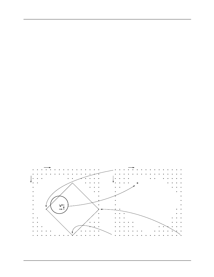
Figure 1. Image resampling geometry showing two-dimensional image rotation and expansion
(XMIN, YMIN)
ORIGINAL (SOURCE) IMAGE
NEW (TARGET) IMAGE
NOTE 2
NOTE 1
NEW PIXEL
x
y
(UMIN, VMIN)
(XMAX, YMAX)
(U0, V0)
(UMAX, VMAX)
65-2302-03
U
V
Notes:
1. Coordinate transformation U, V pixel mapped into X, Y coordinates.
2. Bilinear pixel interpolation walk. New U, V pixel intensity calculated from surrounding X, Y pixel neigborhood.
相關(guān)PDF資料 |
PDF描述 |
|---|---|
| TMC2302AKEC | Image Manipulation Sequencer |
| TMC2302AKEC1 | Image Manipulation Sequencer |
| TMC2330AH5C | Coordinate Transformer 16 x 16 Bit, 40 MOPS |
| TMC2330AH5C1 | Coordinate Transformer 16 x 16 Bit, 40 MOPS |
| TMC2330A | Coordinate Transformer 16 x 16 Bit, 40 MOPS |
相關(guān)代理商/技術(shù)參數(shù) |
參數(shù)描述 |
|---|---|
| TMC2302AKEC | 制造商:FAIRCHILD 制造商全稱:Fairchild Semiconductor 功能描述:Image Manipulation Sequencer |
| TMC2302AKEC1 | 制造商:FAIRCHILD 制造商全稱:Fairchild Semiconductor 功能描述:Image Manipulation Sequencer |
| TMC2330A | 制造商:CADEKA 制造商全稱:CADEKA 功能描述:Coordinate Transformer 16 x 16 Bit, 40 MOPS |
| TMC2330AG1C | 制造商:CADEKA 制造商全稱:CADEKA 功能描述:Coordinate Transformer 16 x 16 Bit, 40 MOPS |
| TMC2330AG1C1 | 制造商:CADEKA 制造商全稱:CADEKA 功能描述:Coordinate Transformer 16 x 16 Bit, 40 MOPS |
發(fā)布緊急采購,3分鐘左右您將得到回復(fù)。