- 您現(xiàn)在的位置:買賣IC網(wǎng) > PDF目錄383876 > T8534 (Lineage Power) Quad Programmable Line Card Signal Processor(四通道可編程線卡信號處理器) PDF資料下載
參數(shù)資料
| 型號: | T8534 |
| 廠商: | Lineage Power |
| 英文描述: | Quad Programmable Line Card Signal Processor(四通道可編程線卡信號處理器) |
| 中文描述: | 四線卡可編程信號處理器(四通道可編程線卡信號處理器) |
| 文件頁數(shù): | 43/48頁 |
| 文件大?。?/td> | 1809K |
| 代理商: | T8534 |
第1頁第2頁第3頁第4頁第5頁第6頁第7頁第8頁第9頁第10頁第11頁第12頁第13頁第14頁第15頁第16頁第17頁第18頁第19頁第20頁第21頁第22頁第23頁第24頁第25頁第26頁第27頁第28頁第29頁第30頁第31頁第32頁第33頁第34頁第35頁第36頁第37頁第38頁第39頁第40頁第41頁第42頁當(dāng)前第43頁第44頁第45頁第46頁第47頁第48頁
Preliminary Data Sheet
July 2000
Signal Processor
T8533/34 Quad Programmable Line Card
Lucent Technologies Inc.
43
Software Interface
(continued)
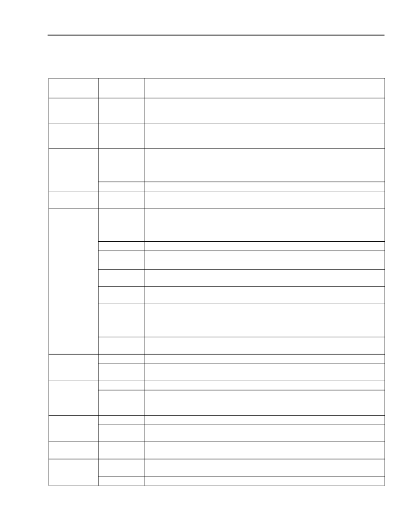
Table 18. Control Bit Definitions
(continued)
Control Name
(Address)
ZEQCTRL
(word
150—152)
GTX1
(word
153—154)
TXBITOFF
(word 155)
Bit
Assignments
Function
0—20
Coefficients for the equalization stage that accommodates current-sensing
SLICs. Defaults to 0x000000.
0—11
Gain control for tweak gain stage in transmit direction. Defaults to 0x051a
(2.11 dB). This is a 12-bit multiply operation with a maximum gain of 4 (12 dB).
5—7
Transmit direction bit offset for the FS signal. Defaults to 0. These 3 bits can be
thought of as the least significant bits (TXOFF contains the more significant bits)
of a bit counter that determines the location of the first bit of the PCM data from
FS.
Load as 0.
Transmit time-slot assignment. Defaults to (16 * channel number).
Each time slot
represents 8 bits, allow for two time slots when using linear mode.
3-state transmit PCM interface. Defaults to 0. A 1 forces the PCM interface into a
high-impedance state during its assigned time slot on the PCM bus. Placing the
channel in standby mode also forces a high-impedance condition on the transmit
interface.
Transmit idle channel code instead of data. Defaults to 0 (off).
Load as 0.
Place idle channel code on receive path. Defaults to 0 (off).
Loopback receive to transmit at PCM conversion interface (
digital loopback 1
).
Defaults to 0 (no loopback).
Loopback transmit to receive at PCM conversion interface (
digital loopback 4
).
Defaults to 0 (no loopback).
Linear/companded. A 1 sets 16-bit linear mode with two adjacent time slots used,
LSB transmitted first. Linear data is in two’s complement form. A 0 sets com-
panded mode with only one time slot used, and MSB transmitted first. Defaults to
0.
μ
-law or A-law. A 0 sets
μ
-law mode, and a 1 sets A-law mode. This bit has no
effect if bit 1 of this address is set to 1. Defaults to 0 (
μ
-law).
Load as 0.
Controls the drivers for the corresponding SLIC latches pins. A 1 enables the pin
as an output. Defaults to 0x0c (bits 2 and 3 set, the rest cleared).
Load as 0.
SLIC latches data. If the corresponding bit in the SLICTS address is set for an
output, the device will drive the corresponding bit according to the contents of this
address. Default is 0.
Not used, ignore on a codec read command addressing this location.
Reports the actual state of the SLIC pins. Anything written to this address is
ignored and will be overwritten by the actual data within one PCM frame (125
μ
s).
Test location for serial interface. This location has no internal use, but merely
latches write data for the purpose of testing the serial interface.
This bit is set to a 1 if a data call is in progress. Do not attempt to write this regis-
ter.
Internal state control bits; do not write and ignore on read.
0—4
0—7
TXOFF
(word 156)
PCMCTRL
(word 157)
7
6
5
4
3
2
1
0
SLICTS
(word 158)
6—7
0—5
SLICWR
(word 159)
6—7
0—5
SLICRD
(word 160)
6—7
0—5
VERIFY
(word 162)
DATACALL
(word 167)
0—7
5
0—4, 6, 7
相關(guān)PDF資料 |
PDF描述 |
|---|---|
| T8533 | Quad Programmable Line Card Signal Processor(四通道可編程線卡信號處理器) |
| T8535A | Quad Programmable Codec Chip Set(四通道可編程編解碼器芯片組) |
| T8536A | Quad Programmable Codec Chip Set(四通道可編程編解碼器芯片組) |
| T8536 | Quad Programmable Codec(四通道可編程編解碼器) |
| T8535 | Quad Programmable Codec(四通道可編程編解碼器) |
相關(guān)代理商/技術(shù)參數(shù) |
參數(shù)描述 |
|---|---|
| T8535B | 制造商:AGERE 制造商全稱:AGERE 功能描述:T8535B/T8536B Quad Programmable Codec |
| T8536B | 制造商:AGERE 制造商全稱:AGERE 功能描述:T8535B/T8536B Quad Programmable Codec |
| T8538B | 制造商:AGERE 制造商全稱:AGERE 功能描述:T8538B Quad Programmable Codec |
| T85471G | 制造商:BITECH 制造商全稱:Bi technologies 功能描述:Thick Film Super Low Profile SIP Resistor Networks |
| T85471J | 制造商:BITECH 制造商全稱:Bi technologies 功能描述:Thick Film Super Low Profile SIP Resistor Networks |
發(fā)布緊急采購,3分鐘左右您將得到回復(fù)。