- 您現(xiàn)在的位置:買賣IC網(wǎng) > PDF目錄385813 > SAA7187 (NXP Semiconductors N.V.) Digital video encoder (DENC2-SQ)(數(shù)字視頻編碼器) PDF資料下載
參數(shù)資料
| 型號: | SAA7187 |
| 廠商: | NXP Semiconductors N.V. |
| 英文描述: | Digital video encoder (DENC2-SQ)(數(shù)字視頻編碼器) |
| 中文描述: | 數(shù)字視頻編碼器(DENC2 -倚)(數(shù)字視頻編碼器) |
| 文件頁數(shù): | 1/18頁 |
| 文件大小: | 197K |
| 代理商: | SAA7187 |
Philips Semiconductors
Clock and synchronization signals of SAA7187 and SAA7188
Application note for digital video encoder
Author: Leo Warmuth
1.0
INTRODUCTION
The devices of the SAA7187/88 family of
video encoders can be used in a variety of
applications differing regarding the signal flow
of timing information. Video timing is defined
by clock signals, synchronization signals and
blanking signals. The video encoder ICs can
generate these signals by itself (master
mode), or can accept them as input (slave
mode). The master/slave characteristic can
be chosen independently for clock and
sync-signals.
1
May 1994
This application note describes the various
clock and synchronization signals, their
functions, and how to select and program
them. The timing relation of some of these
signals is programmable. An application
example shows a possible configuration.
2.0
CLOCK LLC AND CREF
SIGNAL
The SAA7187/88 has two clock signals: LLC
and CREF, functionally compatible with other
Philips digital video processing circuits. LLC
on pin 38 is the Line-Locked-Clock in double
pixel clock frequency. CREF on pin 39 is the
clock qualifier signal, accompanying LLC, to
indicate on which LLC edges the 16 bit wide
YUV data stream transports valid data. CREF
is continuously toggling in pixel rate
frequency, but is not meant as pixel clock.
The transitions of CREF have to maintain
certain setup and hold times relative to clock
LLC (see data sheet). The digital encoder ICs
can generate and provide (drive) the clock
signals by its own by means of the built-in
crystal oscillator, or receive the clock signals
from external. In remote genlock mode, LLC
and CREF can be fed from one of the Philips
digital decoder (DMSD), but must then be
accompanied by RTC signal (real time control
information).
2.1
Built-in clock signal
generator
SAA7187/88 has built-in an optional crystal
oscillator for LLC frequency. A crystal with
double pixel clock frequency as base
frequency, or as third harmonic frequency,
with appropriate auxiliary circuitry, can be
connected between the pins XTALi (input,
pin 41) and XTALo (output, pin 40). The
swing at the XTAL-pins is about 1Vpp, and is
DC-compensated via an internal resistor
between the two pins. Alternatively an
external crystal oscillator could directly drive
into XTALi.
An internal switch, hardware controlled by
CDIR at pin 36, selects whether the IC
provides or receives clock signals LLC and
CREF (see Table 1). If CDIR is low, clock is
taken from the internal crystal oscillator and
the IC outputs LLC at pin 38 and CREF at
pin 39. If CDIR is high, LLC pin and CREF
pin are both switched to be input. The IC then
requires a double pixel clock LLC from
external circuitry at pin 38. Under certain
conditions, CREF input at pin 39 has
data-phase (timing) relevance, but it does not
have directly clock and data qualifying
function.
2.2
In the “clock slave mode” case, i.e., if clock is
provided from external into LLC pin 38, a
CREF-like signal can optionally be applied to
pin 39, but this is not required. If the IC sees
a toggling signal, i.e., edges, at pin 39, CREF
will contribute to re-synchronization of the
internal horizontal counter (once per line) and
– by that – defines the active data phases in
the 16 bit wide YUV input data stream. If
horizontal synchronization from external via
RCV1 or RCV2 is selected, i.e., the encoder
IC is in slave mode regarding horizontal
timing, CREF defines together with the
selected horizontal reference input signal,
when the horizontal trigger counter has to
start. From there the programming parameter
HTRIG (11 bits in subaddress 6E and 6F)
defines the start of the horizontal pixel
counter, and the LSB of the parameter
HTRIG determines one of the two possible
phases of the internally effective CREF
relative to the external provided CREF. The
horizontal reference edge is defined
regarding source and polarity by the various
bits in subaddress 6Chec (see also later in
this application note: re-trigger).
External Clock
If no CREF is provided to the IC, a horizontal
reference signal input is sampled direct with
LLC resolution. The phase of the internal
CREF, and expected valid data phases, are
defined by the selected horizontal reference
edge, and by the LSB of HTRIG. The
horizontal reference edge is defined
regarding source and polarity by the various
bits in subaddress 6Chec (see also later in
this application note: re-trigger).
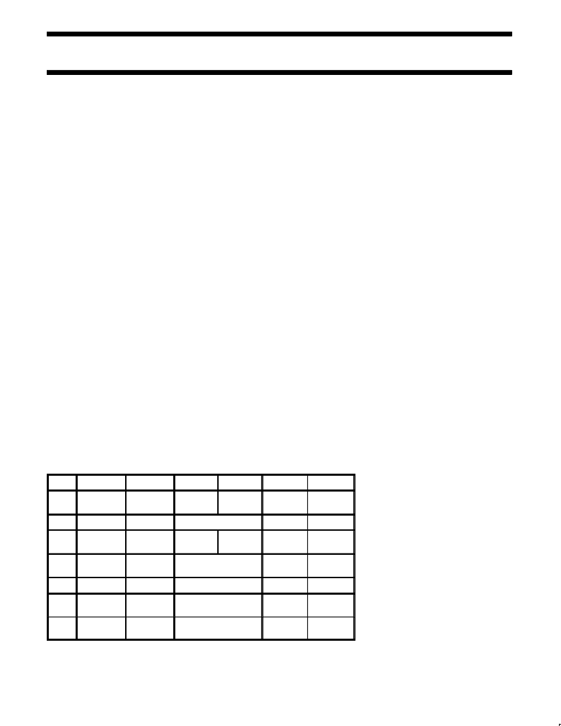
Table 1. Selection of Clock Modes
CDIR
LLC
CREF
XTALo
XTALi
RTCI
RTCE
Pin 36
Pin 38
Pin 39
Pin 40
Pin 41
Pin 43
subaddress
61hex
low
output
output
local crystal
don’t care
don’t care
low
output
output
don’t care
external
oscillator
don’t care
don’t care
high
input
don’t care
but constant
don’t care
don’t care
0
high
input
input
don’t care
don’t care
0
high
input from
DMSD/CGC
don’t care
but constant
don’t care
RTCO from
DMSD
1
high
input from
DMSD/CGC
input from
DMSD/CGC
don’t care
RTCO from
DMSD
1
相關(guān)PDF資料 |
PDF描述 |
|---|---|
| SAA7188A | Digital Video Encoder (DENC2-M)(數(shù)字視頻編碼器(DENC2-M)) |
| SAA7201 | Integrated MPEG2 AVG Decoder(綜合MPEG音頻視頻圖表譯碼器) |
| SAA7201H | Integrated MPEG2 AVG decoder |
| SAA7212 | Integrated MPEG2 AVG Decoder(綜合MPEG音頻視頻圖表譯碼器) |
| SAA7212H | Integrated MPEG AVG decoder |
相關(guān)代理商/技術(shù)參數(shù) |
參數(shù)描述 |
|---|---|
| SAA7187WP | 制造商:NXP Semiconductors 功能描述: |
| SAA7188 | 制造商:PHILIPS 制造商全稱:NXP Semiconductors 功能描述:Digital Video Encoder DENC2-M |
| SAA7188A | 制造商:PHILIPS 制造商全稱:NXP Semiconductors 功能描述:Digital Video Encoder DENC2-M |
| SAA7188AWP | 制造商:NXP Semiconductors 功能描述:COLOR SIGNAL ENCODER, PQCC68 |
| SAA7191B | 制造商:PHILIPS 制造商全稱:NXP Semiconductors 功能描述:Digital Multistandard Colour Decoder, Square Pixel DMSD-SQP |
發(fā)布緊急采購,3分鐘左右您將得到回復(fù)。