- 您現(xiàn)在的位置:買賣IC網(wǎng) > PDF目錄385813 > SAA55XX (NXP Semiconductors N.V.) TV microcontrollers with Closed Captioning (CC) and On-Screen Display (OSD) PDF資料下載
參數(shù)資料
| 型號(hào): | SAA55XX |
| 廠商: | NXP Semiconductors N.V. |
| 英文描述: | TV microcontrollers with Closed Captioning (CC) and On-Screen Display (OSD) |
| 中文描述: | 與隱藏字幕(CC)和屏幕顯示(OSD電視微控制器) |
| 文件頁(yè)數(shù): | 60/84頁(yè) |
| 文件大?。?/td> | 352K |
| 代理商: | SAA55XX |
第1頁(yè)第2頁(yè)第3頁(yè)第4頁(yè)第5頁(yè)第6頁(yè)第7頁(yè)第8頁(yè)第9頁(yè)第10頁(yè)第11頁(yè)第12頁(yè)第13頁(yè)第14頁(yè)第15頁(yè)第16頁(yè)第17頁(yè)第18頁(yè)第19頁(yè)第20頁(yè)第21頁(yè)第22頁(yè)第23頁(yè)第24頁(yè)第25頁(yè)第26頁(yè)第27頁(yè)第28頁(yè)第29頁(yè)第30頁(yè)第31頁(yè)第32頁(yè)第33頁(yè)第34頁(yè)第35頁(yè)第36頁(yè)第37頁(yè)第38頁(yè)第39頁(yè)第40頁(yè)第41頁(yè)第42頁(yè)第43頁(yè)第44頁(yè)第45頁(yè)第46頁(yè)第47頁(yè)第48頁(yè)第49頁(yè)第50頁(yè)第51頁(yè)第52頁(yè)第53頁(yè)第54頁(yè)第55頁(yè)第56頁(yè)第57頁(yè)第58頁(yè)第59頁(yè)當(dāng)前第60頁(yè)第61頁(yè)第62頁(yè)第63頁(yè)第64頁(yè)第65頁(yè)第66頁(yè)第67頁(yè)第68頁(yè)第69頁(yè)第70頁(yè)第71頁(yè)第72頁(yè)第73頁(yè)第74頁(yè)第75頁(yè)第76頁(yè)第77頁(yè)第78頁(yè)第79頁(yè)第80頁(yè)第81頁(yè)第82頁(yè)第83頁(yè)第84頁(yè)
2000 Feb 23
60
Philips Semiconductors
Preliminary specification
TV microcontrollers with Closed Captioning (CC)
and On-Screen Display (OSD)
SAA55xx
18.7.1
S
CREEN COLOUR DISPLAY AREA
This area is covered by the screen colour. The screen
colour display area starts with a fixed offset of 8
μ
s from
the leading edge of the horizontal sync pulse in the
horizontal direction. A vertical offset is not necessary.
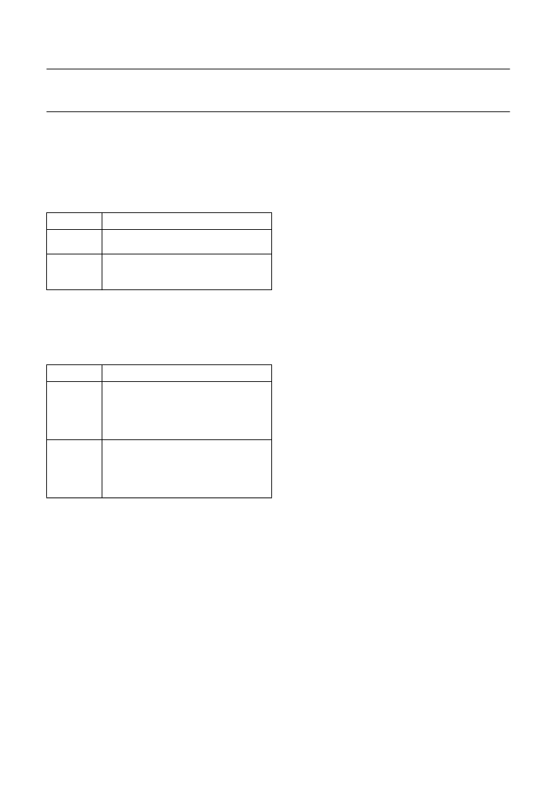
Table 20
Screen colour display area
18.7.2
T
EXT DISPLAY AREA
The text area can be defined to start with an offset in both
the horizontal and vertical direction.
Table 21
Text display area
The horizontal offset is set in the MMR Text Area Start.
The offset is done in full width characters using TAS<5:0>
and quarter characters using HOP<1:0> for fine setting.
The values 00H to 08H for TAS<5:0> will result in a
corrupted display.
The value 09H should also be avoided in the MMR Text
Area Start as corruption of the row 24 display can occur.
Alternative values are C8H or 49H to overcome this
problem.
The width of the text area is defined in the MMR Text Area
End Register by setting the end character value
TAE<5:0>. This number determines where the
background colour of the Text Area will end if set to extend
to the end of the row. It will also terminate the character
fetch process thus eliminating the necessity of a
row end
attribute. This entails however writing to all positions.
The vertical offset is set in the MMR Text Position Vertical.
The offset value VOL<5:0> is done in number of TV scan
lines.
Note that the Text Position Vertical Register should not be
set to 00H as the Display Busy interrupt is not generated
in these circumstances.
18.8
Character set
To facilitate the global nature of the device the character
set has the ability to accommodate a large number of
characters, which can be stored in different matrices.
18.8.1
C
HARACTER MATRICES
The character matrices that can be accommodated in both
display modes are:
(H
×
V
×
planes) 12
×
9
×
1, 12
×
10
×
1, 12
×
13
×
1,
12
×
16
×
1.
These modes allow two colours per character position.
In CC mode two additional character matrices are
available to allow four colours per character.
(H
×
V
×
planes) 12
×
13
×
2, 12
×
16
×
2.
The characters are stored physically in ROM in a matrix of
size either 12
×
10 or 12
×
16.
POSITION
525-LINE
Horizontal
Start at 8
μ
s after leading edge of
horizontal sync for 56
μ
s.
Line 9, Field 1 (321, Field 2) to leading
edge of vertical sync (line numbering
using 625 standard).
Vertical
POSITION
DESCRIPTION
Horizontal
Up to 48 full sized characters per row.
Start position setting from 8 to 64
characters from the leading edge of
horizontal sync. Fine adjustment in
quarter characters.
256 lines (nominal 41 to 297). Start
position setting from leading edge of
vertical sync, legal values are
4 to 64 lines (line numbering using
625 standard).
Vertical
相關(guān)PDF資料 |
PDF描述 |
|---|---|
| SAA6712E | ECONOLINE: RB & RA - Dual Output from a Single Input Rail- Power Sharing on Output- Industry Standard Pinout- 1kVDC & 2kVDC Isolation- Custom Solutions Available- UL94V-0 Package Material- Efficiency to 85% |
| SAA6713AH | XGA analog input flat panel controller |
| SAA6713H | XGA dual input flat panel controller |
| SAA7110 | Digital Multistandard Colour Decoder(數(shù)字多標(biāo)準(zhǔn)彩色譯碼器) |
| SAA7111 | Video Input Processor VIP |
相關(guān)代理商/技術(shù)參數(shù) |
參數(shù)描述 |
|---|---|
| SAA5603 | 制造商:未知廠家 制造商全稱:未知廠家 功能描述: |
| SAA5645 | 制造商:PHILIPS 制造商全稱:NXP Semiconductors 功能描述:Enhanced TV microcontrollers with On-Screen Display OSD |
| SAA5645HL | 制造商:PHILIPS 制造商全稱:NXP Semiconductors 功能描述:Enhanced TV microcontrollers with On-Screen Display OSD |
| SAA5647 | 制造商:PHILIPS 制造商全稱:NXP Semiconductors 功能描述:Enhanced TV microcontrollers with On-Screen Display OSD |
| SAA5647HL | 制造商:PHILIPS 制造商全稱:NXP Semiconductors 功能描述:Enhanced TV microcontrollers with On-Screen Display OSD |
發(fā)布緊急采購(gòu),3分鐘左右您將得到回復(fù)。