- 您現(xiàn)在的位置:買賣IC網(wǎng) > PDF目錄369949 > PCF8832 STN RGB - 384 output column driver PDF資料下載
參數(shù)資料
| 型號(hào): | PCF8832 |
| 英文描述: | STN RGB - 384 output column driver |
| 中文描述: | 超扭曲的RGB - 384列驅(qū)動(dòng)器輸出 |
| 文件頁(yè)數(shù): | 54/76頁(yè) |
| 文件大?。?/td> | 385K |
| 代理商: | PCF8832 |
第1頁(yè)第2頁(yè)第3頁(yè)第4頁(yè)第5頁(yè)第6頁(yè)第7頁(yè)第8頁(yè)第9頁(yè)第10頁(yè)第11頁(yè)第12頁(yè)第13頁(yè)第14頁(yè)第15頁(yè)第16頁(yè)第17頁(yè)第18頁(yè)第19頁(yè)第20頁(yè)第21頁(yè)第22頁(yè)第23頁(yè)第24頁(yè)第25頁(yè)第26頁(yè)第27頁(yè)第28頁(yè)第29頁(yè)第30頁(yè)第31頁(yè)第32頁(yè)第33頁(yè)第34頁(yè)第35頁(yè)第36頁(yè)第37頁(yè)第38頁(yè)第39頁(yè)第40頁(yè)第41頁(yè)第42頁(yè)第43頁(yè)第44頁(yè)第45頁(yè)第46頁(yè)第47頁(yè)第48頁(yè)第49頁(yè)第50頁(yè)第51頁(yè)第52頁(yè)第53頁(yè)當(dāng)前第54頁(yè)第55頁(yè)第56頁(yè)第57頁(yè)第58頁(yè)第59頁(yè)第60頁(yè)第61頁(yè)第62頁(yè)第63頁(yè)第64頁(yè)第65頁(yè)第66頁(yè)第67頁(yè)第68頁(yè)第69頁(yè)第70頁(yè)第71頁(yè)第72頁(yè)第73頁(yè)第74頁(yè)第75頁(yè)第76頁(yè)

2002 Aug 16
54
Philips Semiconductors
Preliminary specification
STN RGB - 384 output column driver
PCF8832
Notes
1.
All timing values are valid within the operating ambient temperature and supply voltage ranges and are referred to
V
IL
and V
IH
with an input voltage swing of V
SS1
to V
DD1
.
Not directly observable at any pin.
C
b
= total capacitance of one bus line in pF.
The input signal rise time and fall time (t
r
and t
f
) are specified at 15 ns or less. When the cycle time is used at
high-speed, the specification is t
r
+ t
f
≤
(T
CYC
t
CCLW
t
CCHW
) or t
r
+ t
f
≤
(T
CYC
t
CCLR
t
CCHR
).
The system cycle time can be derated for different values of V
DD1
. For V
DD1
< 2.5 V the system cycle time can be
calculated as follows:
at V
DD1
= 2.5 V, f
CYC(2.5)
= 6.25 MHz and
f = 0.44 MHz/V then
The input signal rise time and fall time (t
r
and t
f
) are specified at 15 ns or less. When the cycle time is used at
high-speed, the specification is t
r
+ t
f
≤
(T
CYC
t
EH
t
EL
).
The input signal rise time and fall time (t
r
and t
f
) are specified at 15 ns or less.
2.
3.
4.
5.
MHz.
6.
7.
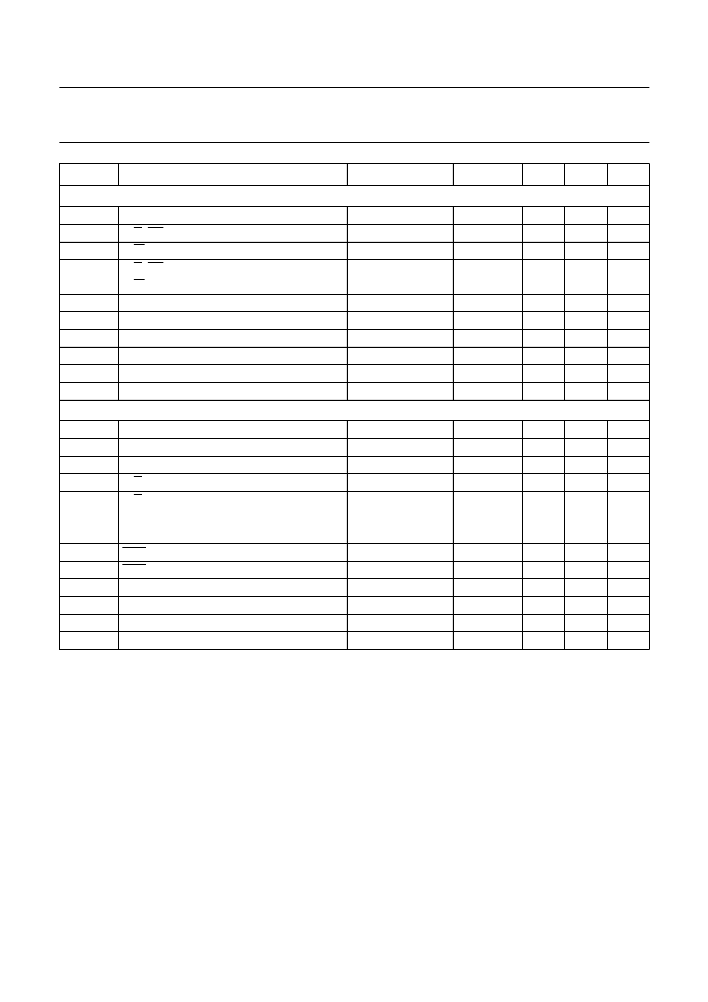
8-bit parallel (6800-type) interface
; note 6; see Fig.57
T
CYC
t
AS1
t
AS2
t
AH1
t
AH2
t
DS
t
DH
t
OH
t
ACC
t
EH
t
EL
Serial interface
; note 7; see Figs 58
,
59 and 60
system cycle time
D/C, CS address set-up time
R/W address set-up time
D/C, CS address hold time
R/W address hold time
D0 to D7 data set-up time
D0 to D7 data hold time
D0 to D7 output disable time
D0 to D7 access time
E pulse width HIGH
E pulse width LOW
160
50
50
10
35
20
10
10
40
60
30
70
ns
ns
ns
ns
ns
ns
ns
ns
ns
ns
ns
C
L
= 50 pF
T
SCYC
t
SHW
t
SLW
t
SAH
t
SAS
t
SDS
t
SDH
t
CSS
t
CSH
t
ODE1
t
ODE2
t
CEH
t
ACC
serial clock SCLK period
SCLK pulse width HIGH
SCLK pulse width LOW
D/C address hold time
D/C address setup time
SDI data set-up time
SDI data hold time
SCE to SCLK set-up time
SCE to SCLK hold time
SDO disable time
SDO disable time
SCLK to SCE hold time
SCLK to SDO access time
160
60
60
70
45
45
50
30
120
25
50
50
100
50
ns
ns
ns
ns
ns
ns
ns
ns
ns
ns
ns
ns
ns
SYMBOL
PARAMETER
CONDITIONS
MIN.
TYP.
MAX.
UNIT
f
CYC(VDD1)
f
CYC(2.5)
0.44
V
DD1
×
×
=
相關(guān)PDF資料 |
PDF描述 |
|---|---|
| PCF8890 | 240 + 1 outputs TFT LCD gate driver |
| PCF93C110 | 32-Bit Microcontroller |
| PCB93C110 | 32-Bit Microcontroller |
| PCG3N60C3W | TRANSISTOR | IGBT | N-CHAN | 600V V(BR)CES | CHIP |
| PCG4AX280MM | FUEHRUNGSSCHIENE LEITERPLATTE 280MM |
相關(guān)代理商/技術(shù)參數(shù) |
參數(shù)描述 |
|---|---|
| PCF8833 | 制造商:PHILIPS 制造商全稱:NXP Semiconductors 功能描述:STN RGB - 132 X 132 X 3 driver |
| PCF88331 | 制造商:PHILIPS 制造商全稱:NXP Semiconductors 功能描述:STN RGB - 132 X 132 X 3 driver |
| PCF88332DA | 制造商:PHILIPS 制造商全稱:NXP Semiconductors 功能描述:STN RGB - 132 X 132 X 3 driver |
| PCF8833U | 制造商:PHILIPS 制造商全稱:NXP Semiconductors 功能描述:STN RGB - 132 X 132 X 3 driver |
| PCF8833U/2DA | 制造商:PHILIPS 制造商全稱:NXP Semiconductors 功能描述:STN RGB - 132 X 132 X 3 driver |
發(fā)布緊急采購(gòu),3分鐘左右您將得到回復(fù)。